Electrical connections – Sterling HS User Manual
Page 17
17
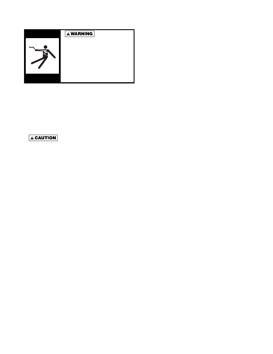
HAZARDOUS VOLTAGE!
DISCONNECT ALL ELECTRIC
POWER INCLUDING REMOTE
DISCONNECTS BEFORE
SERVICING. Failure to
disconnect power before
servicing can cause severe
personal injury or death.
Standard units are shipped for use on 115 volt, 60 hertz
single phase electric power. The motor nameplate and
electrical rating on the transformer should be checked
before energizing the unit heater electrical system. All
external wiring must conform to ANSI/NFPA No. 70-
2006, National Electrical Code (or the latest edition) and
applicable current local codes; in Canada, to the Canadian
Electrical Code, Part 1 CSA Standard C22.1.
Do not use any tools (i.e .
screwdriver, pliers, etc.) across the terminals to
check for power. Use a voltmeter.
It is recommended that the electrical power supply to
each unit heater be provided by a separate, fused and
permanently live electrical circuit. A disconnect switch of
suitable electrical rating for each unit heater should be
located as close to the controls as possible. Each unit
heater must be electrically grounded in accordance with
National Electric Code, ANSI/NFPA No. 70-2006 (or the
latest edition) or CSA Standard C22.1. Sample wiring
connections are depicted in Figures 12 through 22.
OPERATION
Most basic unit heater systems are controlled by a room
thermostat. Locate thermostat on inner wall or column so
that optimum control can be obtained for that area. Set
thermostat for desired temperature.
On steam systems a low limit may be used to prevent
fan from blowing cold air unless the heater has steam
passing through the coil.
Small hot water systems could have the circulating
pump controlled directly by the room thermostat. On
large systems, zone valves could be used to control the
individual unit heater where constant water circulation is
used on the main system.
Horizontal louvers are standard equipment on horizontal
unit heaters, vertical louvers are available as an optional
accessory.
THERMOSTAT WIRING AND LOCATION
NOTICE: The thermostat must be mounted on a
vertical vibration-free surface free from air currents
and in accordance with the furnished instructions.
Mount the thermostat approximately 5 feet (1.5 m) above
the fl oor in an area where it will be exposed to a free
circulation of average temperature air. Always refer to the
thermostat instructions as well as our unit wiring diagram
and wire accordingly. Avoid mounting the thermostat in
the following locations:
1. Cold areas - Outside walls or areas where drafts
may affect the operation of the control.
2. Hot areas - Areas where the sun’s rays, radiation,
or warm air currents may affect control operation.
3. Dead areas - Areas where air cannot circulate
freely, such as behind doors or in corners.
NOTICE: For all wiring connections, refer to the
wiring diagram on the motor nameplate (also refer to
page 18). Should any original wire supplied with the
heater have to be replaced, it must be replaced with
wiring material having a temperature rating of at least
105° C.
ELECTRICAL CONNECTIONS