Location – Sterling HS User Manual
Page 11
11
LOCATION
It is assumed that the design engineer has selected,
sized, and located in the area to be heated. However,
the information given here may be of additional help to
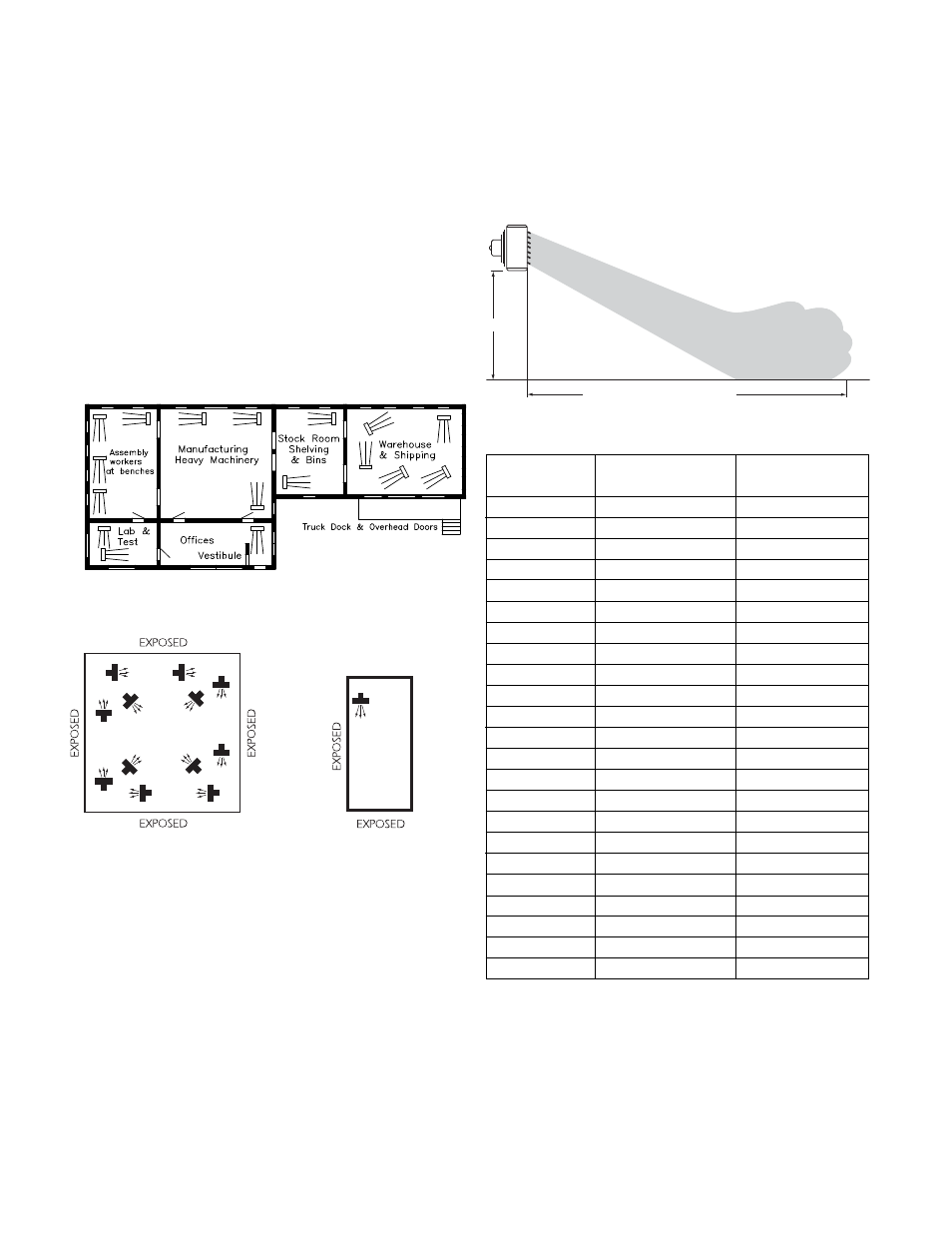
the installer. These sketches indicate suggested basic
locations for different types of unit heaters.
Horizontal unit heaters should be located to give a
circulatory motion, preferably in the outer perimeter of
the building. The units should be spaced to properly
blanket the areas with warm air.
The unit should be suspended from connections
provided in the unit by means of rods. The rods should
then be attached to solid supports of the building.
Figure 5
Figure 6
MOUNTING HEIGHT AND
APPROX. HEAT THROW
Based on 2 PSI (13.8 kPa) steam pressure
and 60°F (16°C) entering air temperature
A large square area with
exposed walls and roof; units
are blanketing all exposed
surfaces.
A small area with exposed
walls requiring one unit.
A narrow area with two
exposed walls either with or
without roof exposure.
H
MAXIMUM DISTANCE OF THROW = T
Table 13
Typical arrangement of unit heaters in
manufacturing plant, showing air fl ow
patterns. Not to scale.
8 (2.4)
8 (2.4)
9 (2.7)
9 (2.7)
8 (2.4)
8 (2.4)
9 (2.7)
9 (2.7)
10 (3.0)
10 (3.0)
10 (3.0)
11 (3.4)
11 (3.4)
12 (3.7)
13 (4.0)
13 (4.0)
13 (4.0)
13 (4.0)
13 (4.0)
14 (4.3)
14 (4.3)
15 (4.6)
15 (4.6)
20 (6.1)
25 (7.6)
29 (8.8)
29 (8.8)
20 (6.1)
24 (7.3)
28 (8.5)
30 (9.1)
30 (9.1)
29 (8.8)
30 (9.1)
38 (11.6)
40 (12.2)
40 (12.2)
54 (16.5)
55 (16.8)
55 (16.8)
53 (16.2)
55 (16.8)
57 (17.4)
57 (17.4)
58 (17.7)
60 (18.3)
108A
118A
125A
136A
18
24
36
48
60
72
84
96
108
120
132
144
156
180
204
240
280
300
360
Model
No.
Maximum
Mounting HT. ft (m)
Approx. Max.
Throw ft (m)