List of parameters – Yokogawa JUXTA MXT User Manual
Page 6
6
IM 77J04X13-01E
2nd Edition Nov 30, 2005-00
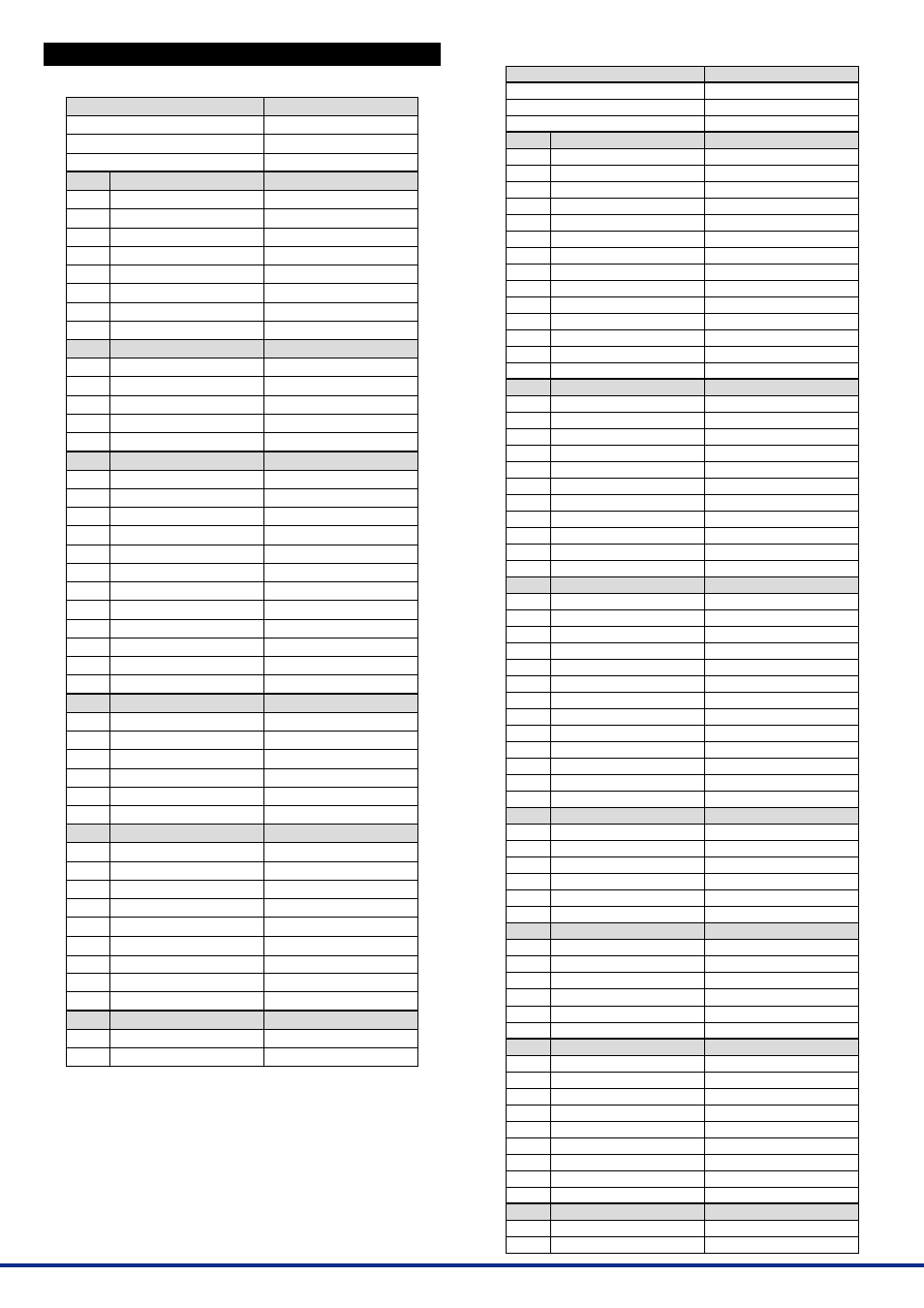
7. LIST OF PARAMETERS
7.1 MXT (except for the function suffix code “A”)
•
•
•
•
•
•
•
•
•
MODEL
TAG NO
SELF CHK
DISPLAY1
INPUT1
INPUT2
INPUT3
OUTPUT1
STATUS
REV NO
MENU REV
SELF CHK
DISPLAY2
INPUT1
INPUT2
INPUT3
OUTPUT1
SELF CHK
SET (I/O)
TAG NO.1
TAG NO.2
COMMENT1
COMMENT2
INP TYPE
IN RESIST
INPUT L_RNG
INPUT H_RNG
OUT1 L_RNG
OUT1 H_RNG
PRGM SELECT
SELF CHK
CONST
CONST
CONST
CONST
CONST
SELF CHK
ADJUST
IN1 ZERO ADJ
IN1 SPAN ADJ
IN2 ZERO ADJ
IN2 SPAN ADJ
IN3 ZERO ADJ
IN3 SPAN ADJ
OUT1ZERO ADJ
OUT1SPAN ADJ
SELF CHK
TEST
OUT1 TEST
SELF CHK
Model
Tag No.
Self-check result
Display 1
Input-1
Input-2
Input-3
Output-1
Status
*1
REV No.
MENU REV
Self-check result
Display 2
Input-1
Input-2
Input-3
Output-1
Self-check result
Setting (I/O)
Tag No.-1
Tag No.-2
Comment-1
Comment-2
Input type
*2
Input resistor
*2
Input low range
Input high range
Output-1 low range
Output-1 high range
Program selection
Self-check result
Fixed Constant of Computing Unit
Fixed constant
Fixed constant
Fixed constant
Fixed constant
Self-check result
Adjustment
Input-1 zero adjustment
Input-1 span adjustment
Input-2 zero adjustment
Input-2 span adjustment
Input-3 zero adjustment
Input-3 span adjustment
Output-1 zero adjustment
Output-1 span adjustment
Self-check result
Test
Forced output-1
Self-check result
Parameter Display
Item
A
A01
A02
A03
A05
A54
A56
A58
A60
B
B01
B02
B03
B05
B60
D
D01
D02
D03
D04
D20
D22
D25
D26
D38
D39
D46
D60
H
H01
H02
H58
H59
H60
P
P08
P09
P10
P11
P12
P13
P26
P27
P60
Q
Q03
Q60
*1: The displayed status is to let the service staff know the past records
of the product.
*2: The parameters are the items to be set at the factory.
7.2 MXT (for the function suffix code “A”)
•
•
•
•
•
•
•
•
•
•
•
•
•
•
•
•
•
•
•
•
•
MODEL
TAG NO
SELF CHK
DISPLAY1
INPUT1
INPUT2
INPUT3
OUTPUT1
T1
T2
T3
T4
DO
LOAD
STATUS
REV NO
MENU REV
SELF CHK
DISPLAY2
INPUT1
INPUT2
INPUT3
OUTPUT1
T1
T2
T3
T4
DO
LOAD
SELF CHK
SET (I/O)
TAG NO.1
TAG NO.2
COMMENT1
COMMENT2
INP TYPE
IN RESIST
INPUT L_RNG
INPUT H_RNG
OUT1 L_RNG
OUT1 H_RNG
PRGM SELECT
CYCLE TIME
SELF CHK
PROGRAM
PROGRAM
PROGRAM
PROGRAM
PROGRAM
SELF CHK
CONST
CONST
CONST
CONST
CONST
SELF CHK
ADJUST
IN1 ZERO ADJ
IN1 SPAN ADJ
IN2 ZERO ADJ
IN2 SPAN ADJ
IN3 ZERO ADJ
IN3 SPAN ADJ
OUT1ZERO ADJ
OUT1SPAN ADJ
SELF CHK
TEST
OUT1 TEST
SELF CHK
Model
Tag No.
Self-check result
Display 1
Input-1
Input-2
Input-3
Output-1
Temporary memory-1
Temporary memory-2
Temporary memory-3
Temporary memory-4
Digital output
Load factor
Status
*1
REV No.
MENU REV
Self-check result
Display 2
Input-1
Input-2
Input-3
Output-1
Temporary memory-1
Temporary memory-2
Temporary memory-3
Temporary memory-4
Digital output
Load factor
Self-check result
Setting (I/O)
Tag No.-1
Tag No.-2
Comment-1
Comment-2
Input type
*2
Input resistor
*2
Input low range
Input high range
Output-1 low range
Output-1 high range
Program selection
Computation cycle
Self-check result
Program of Computing Unit
Program
Program
Program
Program
Self-check result
Fixed Constant of Computing Unit
Fixed constant
Fixed constant
Fixed constant
Fixed constant
Self-check result
Adjustment
Input-1 zero adjustment
Input-1 span adjustment
Input-2 zero adjustment
Input-2 span adjustment
Input-3 zero adjustment
Input-3 span adjustment
Output-1 zero adjustment
Output-1 span adjustment
Self-check result
Test
Forced output-1
Self-check result
Parameter Display
Item
A
A01
A02
A03
A05
A11
A12
A13
A14
A16
A17
A54
A56
A58
A60
B
B01
B02
B03
B05
B11
B12
B13
B14
B16
B17
B60
D
D01
D02
D03
D04
D20
D22
D25
D26
D38
D39
D46
D47
D60
G
G01
G02
G58
G59
G60
H
H01
H02
H58
H59
H60
P
P08
P09
P10
P11
P12
P13
P26
P27
P60
Q
Q03
Q60