Mounting method, Installation locations, External wiring – Yokogawa JUXTA MXT User Manual
Page 2: 1 wall mounting, 2 din rail mounting, 3 using ducts, Warning, Important
2
IM 77J04X13-01E
2nd Edition Nov 30, 2005-00
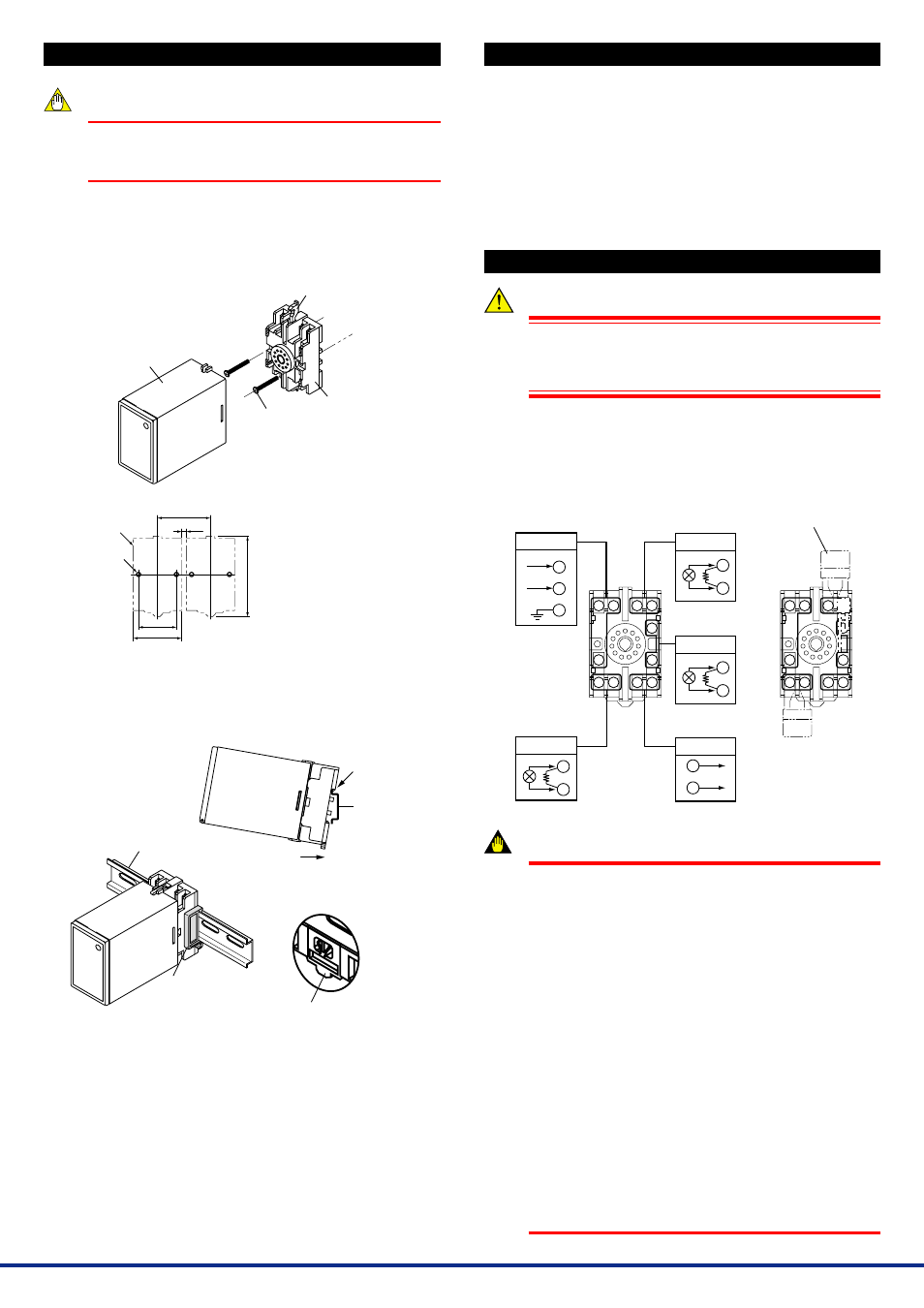
1. MOUNTING METHOD
NOTE
Plug/disconnect the main unit into/from the socket
vertically to the socket face. Otherwise the terminals may
bend and it may cause bad contact.
1.1
Wall Mounting
Unfasten the upper and lower stoppers of the computing unit to discon-
nect the main unit from the socket. Next, anchor the socket onto the
wall with two M4 screws. Then, plug the main unit into the socket and
secure the main unit with the upper and lower stoppers.
Main unit
Mounting
screws
Stopper
Socket
Note:
• When mounting the
computing units close
together, leave a space of at
least 5 mm between them.
• Use the supplied spacer to
keep a space of 5 mm for
DIN rail mounting.
5 or more
2-
л
4.5 or 2-M4
40
Ϯ
0.2
(51)
(85)
Pitch: 56 or more
Socket
Unit: mm
1.2
DIN Rail Mounting
Locate the computing unit so that the DIN rail fits into the upper part of
the DIN-rail groove at the rear of the socket, and fasten the socket us-
ing the slide lock at the lower part of the socket.
Slide lock
Spacer
DIN rail
DIN rail
Fit into here
Push
(Rear of the socket)
1.3
Using Ducts
Wiring ducts should be installed at least 30 mm away from the top or
bottom of the main unit.
2. INSTALLATION LOCATIONS
●
Avoid the following environments for installation locations:
Areas with vibration, corrosive gases, dust, water, oil, solvents, di-
rect sunlight, radiation, a strong electric field, and/or a strong
magnetic field
Installation altitude: 2000 m or less above sea level.
●
If there is any risk of a surge being induced into the power line
and/or signal lines due to lightning or other factors, a dedicated
lightning arrester should be used as protection for both this com-
puting unit and a field-installed device.
●
Operating temperature/humidity range: 0 to 50
Њ
C/5 to 90%RH (no
condensation)
3. EXTERNAL WIRING
WARNING
To avoid the risk of an electric shock, turn off the power
supply and use a tester or similar device to ensure that no
power is supplied to a cable to be connected, before carring
out wiring work.
Wires are connected to the terminals of the computing unit’s socket.
M3.5 screw terminals are provided for the connection of external sig-
nals. Attach a crimp-on lug to each wire for connection to the termi-
nals.
●
Recommended cables: A nominal cross-sectional area of 0.5 mm
2
or thicker for signal cables, and that of 1.25 mm
2
or thicker for
power cables.
10 11
1
2
3
9
8
7
6
5
4
10 11
1
2
3
9
8
7
6
5
4
RES
Power supply
L+
N–
GND
Output
+
-
+
-
Input-1
R
+
-
Input-3
R
R: Receiving resistor
for current input
R: Receiving resistor
for current input
R: Receiving resistor
for current input
+
-
Input-2
R
10
11
1
2
3
4
5
6
7
8
9
Receiving resistor
(for current input)
IMPORTANT
●
The power line and input/output signal lines should be
installed away from noise-generating sources. Other
wise accuracy cannot be guaranteed.
●
The grounding resistance must be 100
Ω
(JIS Class D
grounding). The length and thickness of the grounding
cable should be as short and thick as possible. Directly
connect the lead from the ground terminal (terminal no.
9) of the product to the ground. Do not carry out daisy-
chained inter-ground terminal wiring.
●
Use of the product ignoring the specifications may
cause overheating or damage. Before turning on the
power, ensure the following:
(a) Power supply voltage and input signal value applied
to the product should meet the required
specifications.
(b) The external wiring to the terminals and wiring to
ground are as specifications.
●
Do not operate the product in the presence of
flammable or explosive gases or vapors. To do so is
highly dangerous.
●
The product is sensitive to static electricity; exercise
care in operating it. Before you operate the product,
touch a nearby metal part to discharge static electricity.