Description of front panel, Setting parameters – Yokogawa JUXTA MXT User Manual
Page 3
3
IM 77J04X13-01E
2nd Edition Nov 30, 2005-00
Power Supply and Isolation
Power supply rated voltage:
15-40 V DC or 100-240 V AC 50/60 Hz
Power supply input voltage:
15-40 V DC (
±
20%) or 100-240 V AC (
−
15,
+
10%) 50/60 Hz
Power consumption:
24 V DC 1.9 W
100 V AC 3.6 VA, 200 V AC 5.2 VA
Insulation resistance:
100 M
Ω
or more at 500 V DC between input, output, power sup-
ply, and grounding terminals mutually.
(Each input terminal is not isolated mutually.)
Withstand voltage:
2000 V AC for 1 minute between input, output, power supply and
grounding terminals mutually.
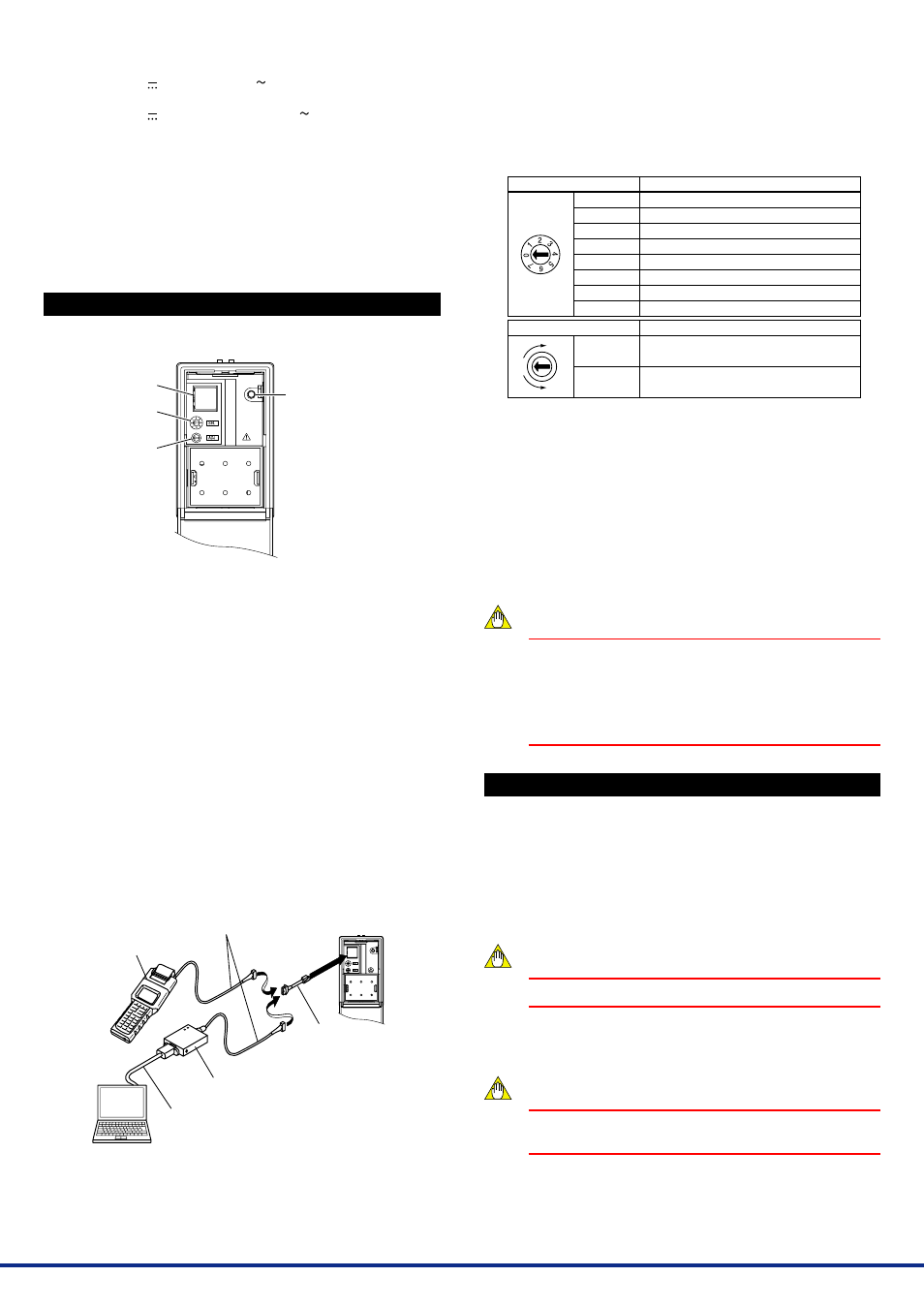
4. DESCRIPTION OF FRONT PANEL
The figure below shows the computing unit of which the front panel
cover is open.
Connector for
communication
Selection switch
Adjustment switch
Operation indicating lamp:
Turns on at power on.
4.1
Operation Indicating Lamp
The operation indicating lamp shows the operation status, abnormali-
ties in a setting, and adjustment operation status by the adjustment
switch on the front panel.
(1) When the lamp is lit:
Power is turned on and the computing unit is in the normal status
provided that the selection switch is set to the position “0.”
(2) When the lamp is blinking rapidly:
The lamp repeats the rapid blinking until the internal processing is
completed during output adjustment by the adjustment switch.
(3) When the lamp is blinking slowly:
The lamp repeats the slow blinking until the computing unit re-
gains its normal status when the following abnormalities occur.
• Abnormalities in a parameter setting
• The selection switch is set to the positions other than “0.”
4.2
Connector for Communication
Use the connector for communication when setting the parameters us-
ing a PC (VJ77 Parameters Setting Tool) or the Handy Terminal.
< How to connect with the setting tool>
Modular jack conversion
adapter (E9786WH)
[Provided with VJ77]
JHT200
Handy Terminal
JUXTA communication cable
with 5-pin connector (F9182EE)
[Provided with VJ77 and JHT200]
Dedicated adapter (E9789HA)
[Provided with VJ77]
PC which is installed
with the VJ77
Dedicated cable (E9786WK)
[Provided with VJ77]
*: Use the VJ77 of version R1.04 or later.
4.3
Selection Switch and Adjustment Switch
The following adjustments can be performed using the switches on the
front panel (selection switch and adjustment switch) without the dedi-
cated setting tool (refer to “4.2 Connector for Communication”).
The adjusted value is saved about 1 second after operating the adjust-
ment switch. Also when the rotation direction of the adjustment switch
is changed, the adjusted value becomes effective about 1 second after
the change.
Position of selection switch
0
1
2
3
4
5
6
7
Rotation direction of adjustment switch
Clockwise
Counterclockwise
Item to be adjusted
No function
Output zero adjustment
Output span adjustment
No function
No function
No function
No function
No function
Adjustment operation
Increase of output adjusted value
Decrease of output adjusted value
[Adjusted volume by the adjustment switch]
One click changes about 0.005% of output range.
4.3.1 Adjusting Output Using the Switches on the Front Panel
(1) Output zero adjustment
Turn the selection switch to “1.” Then turn the adjustment switch
clockwise to increase the output, or turn it counterclockwise to de-
crease the output.
(2) Output span adjustment
Turn the selection switch to “2.” Then turn the adjustment switch
clockwise to increase the output, or turn it counterclockwise to de-
crease the output.
NOTE
•
Be sure to set the selection switch back to the position
“0” after each adjustment. Otherwise it may cause an
incorrect operation or malfunction because the
positions other than “0” are adjustment modes.
•
When the selection switch is set to the positions other
than “0”, the setting tool can not be used for the setting.
5. SETTING PARAMETERS
Set the parameters using a PC (VJ77 Parameters Setting Tool) or the
Handy Terminal. Refer to “7. List of Parameters” in this manual and the
User’s Manual for VJ77 PC-based Parameters Setting Tool (IM
77J01J77-01E) or the User’s Manual for JHT200 Handy Terminal (IM
JF81-02E). Parameters are indicated inside the [ ].
■
Setting Input Range
Set the 0% value of input range in [D25: INPUT L_RNG] and the 100%
value of input range in [D26: INPUT H_RNG].
NOTE
Changing the input range resets the input adjusted value.
■
Setting Output Range
Set the 0% value of output range in [D38: OUT1 L_RNG] and the 100%
value of output range in [D39: OUT1 H_RNG].
NOTE
Changing the output range resets the output adjusted
value.