Maintenance, 1 calibration apparatus, 2 calibration procedure – Yokogawa JUXTA VJXS User Manual
Page 7
7
IM 77J01X11-01E
2nd Edition
Nov 30,2005-00
8. MAINTENANCE
The product starts running immediately when the power is turned on;
however, it needs 10 to 15 minutes of warm-up before it meets the
specified performance.
8.1
Calibration Apparatus
●
A DC voltage/current standard (Yokogawa 7651 or the equivalent)
●
A digital multimeter (Yokogawa 7561 or the equivalent)
●
A precision resistor of 250
⍀
±
0.01%, 1 W
●
Setting tool for adjustment (Refer to “4.1 Connector for Communi-
cation” in this manual.)
8.2
Calibration Procedure
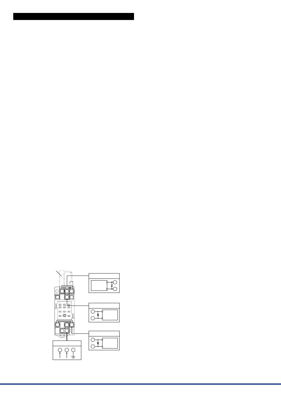
(1) Connect the instruments as shown below. First adjust the output-
1 signal and then the output-2 signal.
(2) Use the DC voltage/current standard and apply input signals
equivalent to 0, 25, 50, 75, and 100% of input span to the comput-
ing unit.
(3) Check to see the output values obtained from the computation of
each input are within the specified accuracy rating. “R” is used for
current output.
●
Use the setting tool (VJ77 Parameters Setting Tool or JHT200
Handy Terminal) to adjust the input/output signals.
Input Adjustment Procedure
(1) Input the value equivalent to 0% value of input range.
(2) Call the display item (A: DISPLAY1) to check the input value in
A01: INPUT1.
(3) If the adjustment is necessary, call the adjustment item (P: AD-
JUST).
(4) Select P08: IN1 ZERO ADJ to enter the adjustment mode. Select
EXECUTE (adjustment) for adjustment. (If RESET is selected,
the adjusted value is reset to the factory-set default.)
(5) Input the value equivalent to 100% value of input range.
(6) Call the display item (A: DISPLAY1) to check the input value in
A01: INPUT1.
(7) If the adjustment is necessary, call the adjustment item (P: AD-
JUST).
(8) Select P09: IN1 SPAN ADJ to enter the adjustment mode. Select
EXECUTE (adjustment) for adjustment. (If RESET is selected,
the adjusted value is reset to the factory-set default.)
Output Adjustment Procedure
(1) When adjusting 0% value of output-1, call the adjustment item (P:
ADJUST) to select P26: OUT1ZERO ADJ.
(2) If there is a positive deviation, correct it by setting a negative
value to offset the deviation. If there is a negative deviation, cor-
rect it by setting a positive value.
*:
The 100% value of output-1 and 0% / 100% values of output-2
can be adjusted by the same operation as the above.
For adjustment using a setting tool, refer to the User’s Manual for
each setting tool and “7. List of Parameters” in this manual.
User’s Manual for VJ77 [Document No.: IM 77J01J77-01E]; how-
ever, use the VJ77 of version R1.04 or later.
User’s Manual for JHT200 [Document No.: IM JF81-02E]
10
11
3
2
1
4
5
6
7
8
9
Power supply
11
10
8
L+
N–
GND
Shunt resistor
(External receiving
resistor for
current input)
R: Receiving resistor
for current input
R
1
3
Input
Ϫ
ϩ
2
5
Output-2
R
Output-1
7
9
R
Ϫ
ϩ
Ϫ
ϩ
R: 250
⍀
precision resistor
for current output
R: 250
⍀
precision resistor
for current output
Digital
multimeter
Digital
multimeter
DC voltge/
current
standard