External wiring, Warning, Important – Yokogawa JUXTA VJCE-01A User Manual
Page 6
6
All Rights Reserved. Copyright © 1999, Yokogawa M&C Corporation
IM 77J01C51-11E
1st Edition July 23,2004-00
4. EXTERNAL WIRING
4.1
Field Side Wiring and Wiring of Power Supply and Ground
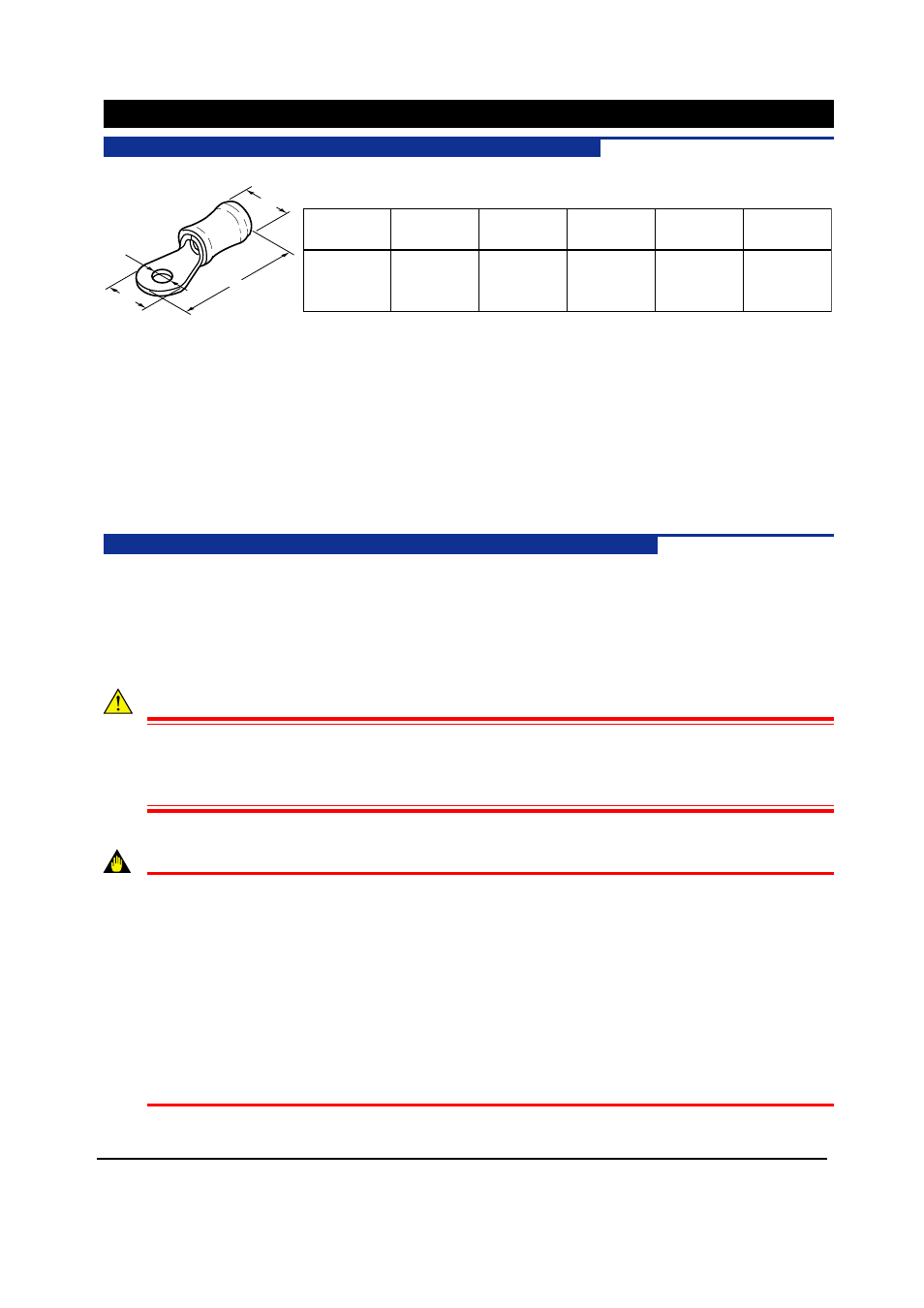
Flexible twisted cable and durable round crimp-on terminals of good contact are recommended to use.
0.75
mm
2
0.9
mm
2
M3.5
3.7 or more
6.9 or less
About 19
3.2 or more
1.25
mm
2
2.0
mm
2
Cross sectional
area
Screw
л
D1
Hole dia.
(mm)
A
Terminal out dia.
(mm)
L
Terminal length
(mm)
øD2
Insulation coating
(mm)
L
л
D1
A
л
D2
4.1.1
Signal cable
Nominal cross-sectional area of conductor:
0.75 to 2 mm
2
Example of suitable cable:
Vinyl code (VSF) twisted cable (JIS C3306)
4.1.2
Power cable
Nominal cross-sectional area of conductor:
1.25 to 2 mm
2
Example of suitable cable:
600V vinyl code (IV) twisted cable (JIS C3307)
Vinyl insulated cable (KIV) (JIS C3316)
4.1.3
Ground cable
Nominal cross-sectional area of conductor:
2 mm
2
Example of suitable cable:
600 V vinyl code (IV) twisted cable (JIS C3307)
Vinyl insulated cable (KIV) (JIS C3316)
4.2
Field Side Input/Output Terminals, Piping and System Side Wiring
Assignment of Input/Output Terminals on and after page 7 shows relation between VJCE-01A field side input/output
terminals and signal conditioner input /output signal at the terminals. Field side input/output terminals are M3.5
screws.
Connect input air pressure signal of VJF1 to connecting hole of front face of signal conditioner directly.
Connect power and ground cables to power terminals of VJCE-01A. Power would internally be distributed to respec-
tive signal conditioners.
WARNING
It is recommended that CT protector (CTG-5) be attached to the current input terminals connected to the
secondary side of the CT when mouning VJB1 (CT transmitter) on VJCE-01A. Since a high potential
develops over the secondary side, the CT may burn and break if you unplug the VJB1 from the VJCE-
01A while the VJB1 is turned on and it has no CT protector.
IMPORTANT
●
Ensure the followings before turning on the power. Use of signal conditioners of VJ series ignoring
the specifications may cause overheating or damage to VJCE-01A and signal conditioners.
·
Power supply voltage and input signal value applied to VJCE-01A and signal conditioners should
meet the required specifications.
·
The external wiring to the terminals is as specifications.
●
Do not operate the product in the presece of flammable or explosive gases or vapors. To do so is
highly dangerous.
●
Many semi-conductor integrated circuit parts are used for signal conditioners. Take care of static
electricity trouble at the maintenance or change of setting for the signal conditioners.
●
The grounding resistance must be 100
Ω
(JIS Class D grounding). The length and thickness of the
grounding cable should be as short and thick as possible. Directly connect the lead from the ground
terminal of the product to the ground. Do not carry out daisy-chained inter-ground terminal wiring.