2 condition of installation, 3 installation – Yokogawa JUXTA VJCE-01A User Manual
Page 5
5
All Rights Reserved. Copyright © 1999, Yokogawa M&C Corporation
IM 77J01C51-11E
1st Edition July 23,2004-00
3.2
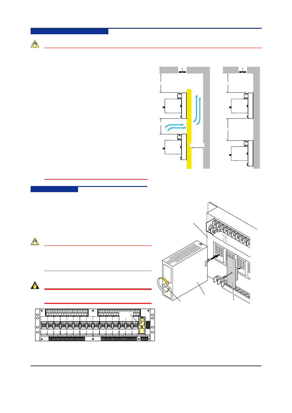
Condition of Installation
NOTE
(1) Secure space for top and bottom to avoid
heating.
●
Apart more than 100 mm from the floor
board.
●
Apart more than 100 mm from panel top
and make air exhaust hole or set cooling
fan at panel upper.
●
If wall stands at back in case of rack
mounting, apart more than 60mm from the
wall for ventilation.
(2) Take enough space for front and side faces
so as not to interfere wiring, piping and
maintenance area.
(3) In case storing in cabinet, air cooling is
compulsorily required to prevent from raise of
temperature.
(4) Do not install it on the heating materials.
(5) In case of installing the VJCE-01A one above
another to up and down direction, take
installation space as shown in the figure on
the right. (78 mm for rack mounting, 128 mm
for wall mounting)
3.3
Installation
3.3.1
Installation of VJCE-01A
Use four (4) M5 screws for installation.
3.3.2
Installation of signal conditioners
Connect the pin on the back of the signal conditioner to the
VJCE-01A connector as shown in the figure on the right. Then
tighten the fixing screw on the front of the signal conditioner.
NOTE
Insert and pull out the signal conditioner vertically
to VJCE. Inserting and pulling it out slantwise may
make the pin bent and cause a failure such as a
bad contact.
IMPORTANT
Only one VJET can be mounted in slot 16 of VJCE-
01A. Do not mount it in other slots.
VJET
Cooling fan or exhaust hole
Cooling fan or
exhaust hole
●
19 inches Rack Mounting
●
Wall Mounting
Unit : mm
100 or more
78 or more
60 or more
100 or more
128 or more
Signal Conditioner
Fixing screw
VJCE
Blank Plate (Option)
Parts Number : T9093TT