Vjce-014 – Yokogawa JUXTA VJCE User Manual
Page 9
9
All Rights Reserved. Copyright © 1999, Yokogawa M&C Corporation
IM 77J0C51-01E
2nd Edition July 23,2004-00
Mountable Signal Conditioners
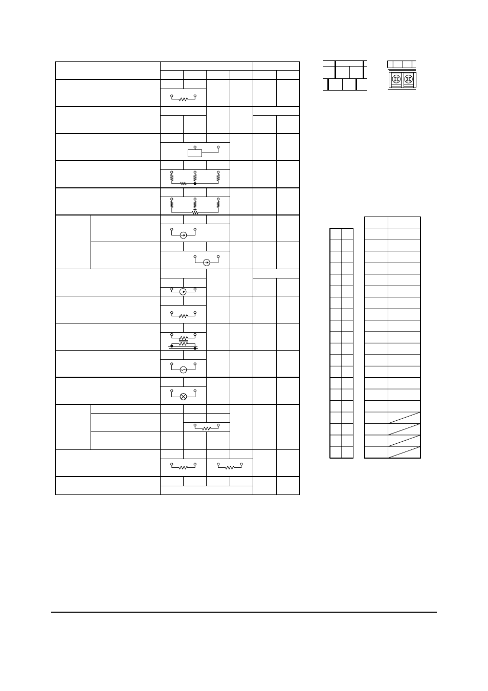
Input Terminal
1
3
4
6
7
9
Output-1 Terminal
VJH1, VJH7, VJHF, VJHR
VJQ0, VJQ7
VJXS, VJX7
VJC1 (*1)
VJT6
VJU7 (TC or mV input)
VJR6
VJU7 (RTD input)
VJS2, VJS7
VJA1
VJA5
VJA7
VJA4 (*1)
VJB1
VJG1
VJB3
VJD1
VJP1
VJP4
VJP8
VJQ2
VJQ8
VJSS
VJF1
ϩ
Ϫ
Channel-1
ϩ
Ϫ
ϩ
Ϫ
A
B
B
PS
ϩ
Ϫ
N.C.
N.C.
ϩ
Ϫ
A
Ϯ
V
Ϯ
V
Ϯ
N.C.
ϩ
Ϫ
PS
ϩ
ϩ
Ϫ
PS
ϩ
ϩ
Ϫ
A/V
Ϯ
Channel-1
ϩ
Ϫ
ϩ
Ϫ
ϩ
Ϫ
N.C.
N.C.
N.C.
N.C.
100% CENTER
0%
ϩ
Ϫ
ϩ
Ϫ
ϩ
Ϫ
ϩ
Ϫ
ϩ
Ϫ
ϩ
Ϫ
ϩ
Ϫ
ϩ
Ϫ
ϩ
Ϫ
ϩ
Ϫ
ϩ
Ϫ
N.C.
N.C.
N.C.
N.C.
Input through one-touch fitting
л
6 of the VJF1.
N.C.
N.C.
N.C.
N.C.
N.C.
N.C.
N.C.
N.C.
N.C.
N.C.
N.C.
N.C.
N.C.
N.C.
N.C.
N.C.
N.C.
N.C.
Channel-1
ϩ
Ϫ
Channel-1
ϩ
Ϫ
ϩ
Ϫ
When using internal power
supply
When using external power
supply (When used as an iso-
lator)
Non-voltage contact / Voltage contact
Internally powered current pulse
(two-wire system)
Internally powered voltage pulse
(three-wire system)
*1: Only 1-channel type of VJC1 and VJA4 can be mounted on VJCE.
*2: When receiving current input (current pulse), external shunt resistor (receiving resistor) is required.
(*2)
(*2)
(*2)
(*2)
“N.C.” in the table denotes unassigned terminals.
RJC
L
N
40
39
38
37
36
35
34
33
32
31
30
29
28
27
26
25
24
23
22
21
20
19
18
17
16
15
14
13
12
11
10
09
08
07
06
05
04
03
02
01
40
1
+
39
–
38
2
+
37
–
36
3
+
35
–
34
4
+
33
–
32
5
+
31
–
30
6
+
29
–
28
7
+
27
–
26
8
+
25
–
24
9
+
23
–
22
10
+
21
–
20
11
+
19
–
18
12
+
17
–
16
13
+
15
–
14
14
+
13
–
12
15
+
11
–
10
16
+
09
–
08
07
06
05
04
03
02
01
Pin No.
Slot No.
CN1
CN1
Connector's Pin Assignment
Note: The figure represents the
connector when viewed from
the connector cable.
Input Terminals
Output-1 Teminals
SLOT*
1
7
*
9
4
3
6
“*” in the figure above denotes a slot number.
Slots are numbered from 1 to 16, beginning with
the leftmost slot, when viewed from the VJCE
front.
●
VJCE-014