Installation of vjce, 1 environmental conditions, 2 condition of installation – Yokogawa JUXTA VJCE User Manual
Page 5: 3 installation
5
All Rights Reserved. Copyright © 1999, Yokogawa M&C Corporation
IM 77J0C51-01E
2nd Edition July 23,2004-00
3. INSTALLATION OF VJCE
The VJCE can be installed horizontally on 19 inches rack complies with JIS/EIA standards, or horizontally on the
wall. Under the conditions mentioned in Article 3.2, a maximum of 5 mounting bases can be installed on one side of
the cabinet.
3.1
Environmental Conditions
3.1.1 Ambient temperature and humidity
Ambient temperature and humidity during operation of the instruments would be as follows:
Temperature: 0 to 50
°
C, Humidity: 5 to 90% RH
3.1.2 Vibration condition
Vibration of installation place would be less than 2m/s
2
at 10 to 150Hz
3.1.3 Air purification degree
Air dirty is desirous to be less than 0.2mg/m
3
. Also, corrosive gas such as hydrogen sulfide, sulfurous acid gas, chlo-
rine and conductive dust such as iron and carbon are desirous to be as little as possible.
(Note)
Permissible limit of hydrogen sulfide (H
2
S) and sulfurous acid gas (SO
2
) would be as standard of JEIDA-29 (1979) CLASS S1*.
JEIDA:
Japan Electronic Industrial Development Association JEIDA-29 (1979) CLASS S1
H
2
S: 0.01ppm or less, SO
2
: 0.05ppm or less (Ambient temperature: 25
°
C
±
5
°
C, ambient humidity: 40 to 80%RH)
3.2
Condition of Installation
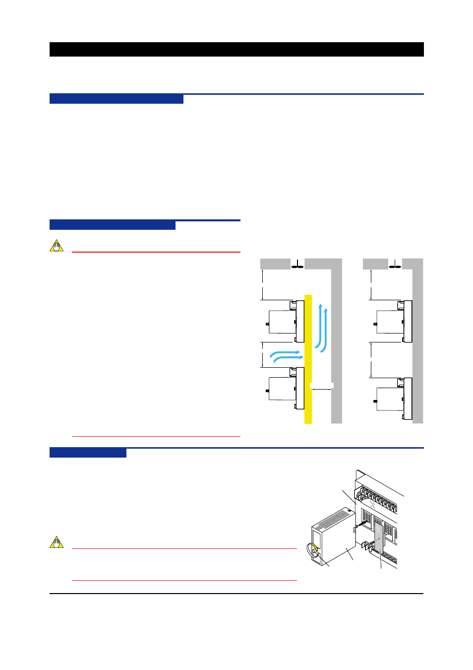
NOTE
(1) Secure space for top and bottom to avoid heating.
●
Apart more than 100 mm from the floor board.
●
Apart more than 100 mm from panel top
and make air exhaust hole or set cooling
fan at panel upper.
●
If wall stands at back in case of rack
mounting, apart more than 60mm from the
wall for ventilation.
(2) Take enough space for front and side faces so as
not to interfere wiring, piping and maintenance area.
(3) In case storing in cabinet, air cooling is
compulsorily required to prevent from raise of
temperature.
(4) Do not install it on the heating materials.
(5) In case of installing the VJCE one above
another to up and down direction, take
installation space as shown in the figure on the
right. (78 mm for rack mounting, 128 mm for
wall mounting)
3.3
Installation
3.3.1
Installation of VJCE
Use four (4) M5 screws for installation.
3.3.2
Installation of signal conditioners
Connect the pin on the back of the signal conditioner to the VJCE connector
as shown in the figure on the right. Then tighten the fixing screw on the front
of the signal conditioner.
NOTE
Insert and pull out the signal conditioner vertically to VJCE.
Inserting and pulling it out slantwise may make the pin bent and
cause a failure such as a bad contact.
Cooling fan or exhaust hole
Cooling fan or
exhaust hole
●
19 inches Rack Mounting
●
Wall Mounting
Unit : mm
100 or more
78 or more
60 or more
100 or more
128 or more
Signal Conditioner
Fixing screw
VJCE
Blank Plate (Option)
Parts Number : T9093TT