Maintenance, Safety and emc standards, 1 calibration apparatus – Yokogawa JUXTA VJSS User Manual
Page 4: 2 calibration procedure, Caution
4
IM 77J01S11-01E 2nd Edition Mar, 02. 2012-00
7. MAINTENANCE
The product starts running immediately when the power is turned
on; however, it needs 10 to 15 minutes of warm-up before it
meets the specified performance.
7.1 Calibration Apparatus
• Two DC voltage/current standard (Yokogawa 7651 or the
equivalent)
• A digital multimeter (Yokogawa 7561 or equivalent)
• A precision resistor of 250 Ω ±0.01%, 1W
• Setting tool for adjustment (Refer to
Communication” in this manual.)
7.2 Calibration Procedure
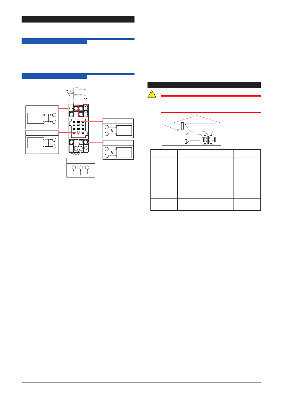
1. Connect the instruments as shown below.
10
11
3 2 1
4
5
6
7
8
9
11
10
8
L
+
N
–
GND
1
3
+
–
+
–
Ri
Ri
4
6
Voltage and
current
generator
Voltage and
current
generator
2
5
7
9
R
R
DMM
DMM
+
–
+
–
Power Supply
External receiving resistor
(Shunt resistor
for current input)
Input-1
Ri: External receiving resistor
for current input
Ro: For current output using
250 Ω precision resistor
Input-2
Output-2
Output-1
2. For the high signal selector: VJSS-H□□-□□□0
Apply the input signal equivalent to -5 to 0% of the input span
to one of two inputs of the converter from a voltage current
source.
For the low signal selector: VJSS-L □□ - □□□ 0
Apply the input signal equivalent to 100 to 105% of the input
span to one of two inputs of the converter from a voltage
current source.
3. Apply the input signal equivalent to 0, 25, 50, 75, and 100%
of the input span to one of two inputs of the converter from a
voltage current source.
4. Check to see the corresponding output voltages are 0, 25, 50,
75, and 100% respectively and within the specified accuracy
rating. “R” is used for current output.
• Use the setting tool (VJ77 Parameter Setting Tool or JHT200
Handy Terminal) to adjust the input/output signals.
Input Adjustment Procedure
(1) Input the value equivalent to 0% value of the input range to
the high/low signal selector.
(2) Call the display item (A: DISPLAY1) to check the input value
in A01: INPUT1.
(3) If the adjustment is necessary, call the adjustment item (P:
ADJUST).
(4) Select P08: IN1 ZERO ADJ to enter the adjustment mode.
Select EXECUTE (adjustment) for adjustment. (If RESET is
selected, the adjusted value is reset to the factory-set default.)
(5) Input the value equivalent to 100% value of input range.
(6) Call the display item (A: DISPLAY1) to check the input value
in A01: INPUT1.
(7) If the adjustment is necessary, call the adjustment item (P:
ADJUST).
(8) Select P09: IN1 SPAN ADJ to enter the adjustment mode.
Select EXECUTE (adjustment) for adjustment. (If RESET is
selected, the adjusted value is reset to the factory-set default.)
• Input-2 can be adjusted by the same operation as the above.
Output Adjustment Procedure
(1) When adjusting 0% value of output, call the adjustment item
(P:ADJUST) to select [P26:OUT1ZERO ADJ].
(2) If there is a positive deviation, correct it by setting a negative
value to offset the deviation. If there is a negative deviation,
correct it by setting a positive value.
*: The 100% value of output-1 and the 0%/100% value of
output-2 can be adjusted by the same operation as the above.
For adjustment using a setting tool, refer to the User’s Manual
for each setting tool and
“6. LIST OF PARAMETERS” in this
manual.
User’s Manual for VJ77 [Document No.: IM 77J01J77-01E];
however, use the VJ77 of version R1.04 or later.
User’s Manual for JHT200 [Document No.: IM JF81-02E]
SAFETY AND EMC STANDARDS
CAUTION
This instrument is for Measurement Category I (CAT.I).
Do not use it for measurements in locations falling
under Measurement Categories II, III, and IV.
Internal Wiring
Outlet
Entrance
Cable
III
T
I
II
IV
Measurement
category
Description
Remarks
I
CAT.I For measurements performed
on circuits not directly connected
to MAINS.
II
CAT.II For measurements performed
on circuits directly connected to
the low-voltage installation.
Appliances,
portable
equipments,
etc.
III
CAT.III For measurements performed in
the building installation.
Distribution
board, circuit
breaker, etc.
IV
CAT.IV For measurements performed
at the source of the low-voltage
installation.
Overhead
wire, cable
systems, etc.
An analog input signal is measurement category I (CAT.I).
Rated transient overvoltage: 1500 V
(Note)
Note
This is a reference safety standard value for
Measurement Category I of IEC/EN/CSA/UL61010-1.
This value is not necessarily a guarantee of instrument
performance.
EMC standards: Complies with EN61326.
The above conformed instrument is only for voltage of 15 to 30
V DC.
* The instrument continues to operate at a measurement
accuracy of within ±20% of the range during testing.