Mounting method, Installation location, External wiring – Yokogawa JUXTA VJSS User Manual
Page 2: 1 wall mounting, 2 din rail mounting, 3 mounting using, 4 using a duct, Warning
2
IM 77J01S11-01E 2nd Edition Mar, 02. 2012-00
1. MOUNTING METHOD
Note
Insert/pull out the main unit into/from the socket
vertically to the face of socket. Otherwise the terminals
are bent and it may cause a bad contact.
1.1 Wall Mounting
Loosen the main unit-fixing screw of the product and pull out the
main unit from the socket. Fix the socket on the wall with screws.
Next, insert the main unit into the socket and fasten the main unit
with the main unit-fixing screw.
29.5 or more
22±0.2
2-M4 or
2-ø4.5 or more
Mounting Dimensions
59±0.3
Unit: mm
Main unit-fixing
screw
Socket
Main unit
Threaded hole for
fixing the main unit
Mounting
screws
1.2 DIN Rail Mounting
Insert a DIN rail into the upper part of the DIN rail groove on the
rear of the socket, and then slide the slide lock at the lower part of
the socket upwards until the socket is fixed into position as shown
below
DIN rail
DIN rail
(Rear of socket)
Slide look
DIN rail
Fit into here
Push
1.3 Mounting Using
When using a multi-mounting base, see the User’s Manual for
VJCE (VJCE Mounting Base).
1.4 Using a Duct
When using a wiring duct, install the duct at leaset 30 mm away
from the top and bottom faces of the main unit.
2. INSTALLATION LOCATION
• Avoid the following environments for installation locations:
Areas with vibration, corrosive gases, dust, water, oil, solvents,
direct sunlight, radiation, a strong electric field, and/or a strong
magnetic field, altitude of more than 2000m above sea level.
• If there is any risk of a surge being induced into the power
line and/or signal lines due to lightning or other factors, a
dedicated lightning arrester should be used as protection for
both this converter and a field-installed device.
• Operating temperature/humidity range: 0 to 50C/5 to 90%RH
(no condensation)
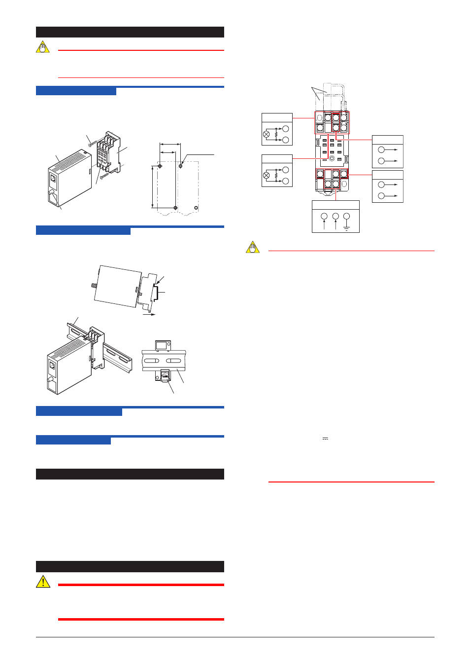
3. EXTERNAL WIRING
WARNING
Be sure to turn OFF the power supply before wiring to
avoid the risk of electric shock. Use a tester or similar
device to ensure that no power is being supplied to a
cable to be connected.
Wiring should be connected to the terminals on the socket
of the product. The terminals for external connections are of
M3 screws. Use crimp-on terminal lugs for connections to the
terminals.
•
Recommended cables: A nominal cross-sectional area of
0.5 mm2 or thicker for signal cables, and that of 1.25 mm2 or
thicker for power cables.
10
11
3 2 1
4
5
6
7
8
9
Power Supply
11
10
8
L
+
N
–
GND
1
3
+
–
+
–
+
–
+
–
External receiving resistor
(Shunt resistor
for current input)
Input-1
R: External receiving resistor
for current input
R
R
4
6
Input-2
Output-2
2
5
Output-1
7
9
Note
●
Do not use output-2 for the single-output type.
●
The power line and input/output signal lines should
be installed away from noise-generating sources.
Other wise accuracy cannot be guaranteed.
●
The grounding resistance must be 100 Ω (JIS
Class D grounding). The length and thickness of
the grounding cable should be as short and thick
as possible. Directly connect the lead from the
ground terminal (terminal no. 8) of the product to the
ground. Do not carry out daisychained inter-ground
terminal wiring
●
Use of the product ignoring the specifications may
cause overheating or damage. Before turning on the
power, ensure the following:
Power supply voltage and input signal value applied to
the product should meet the required specifications.
The external wiring to the terminals and wiring to ground
are as specifications.
●
Do not operate the product in the presence of
flammable or explosive gases or vapors. To do so is
highly dangerous.
●
The product is sensitive to static electricity;
exercise care in operating it. Before you operate
the product, touch a nearby metal part to discharge
static electricity.
●
For 15-30 V DC (±20%) power supply, as a safety
measure, always install a circuit breaker (an IEC
60947-compatible product, 1 A, 30 V DC) in an easily
accessible location near the instrument. Moreover,
provide indication that the switch is a device for
turning off the power to the instrument.