Attachment positions and channel numbers – Yokogawa PC-Based MX100 User Manual
Page 2
2
IM MX100-74E
Attachment Positions and Channel Numbers
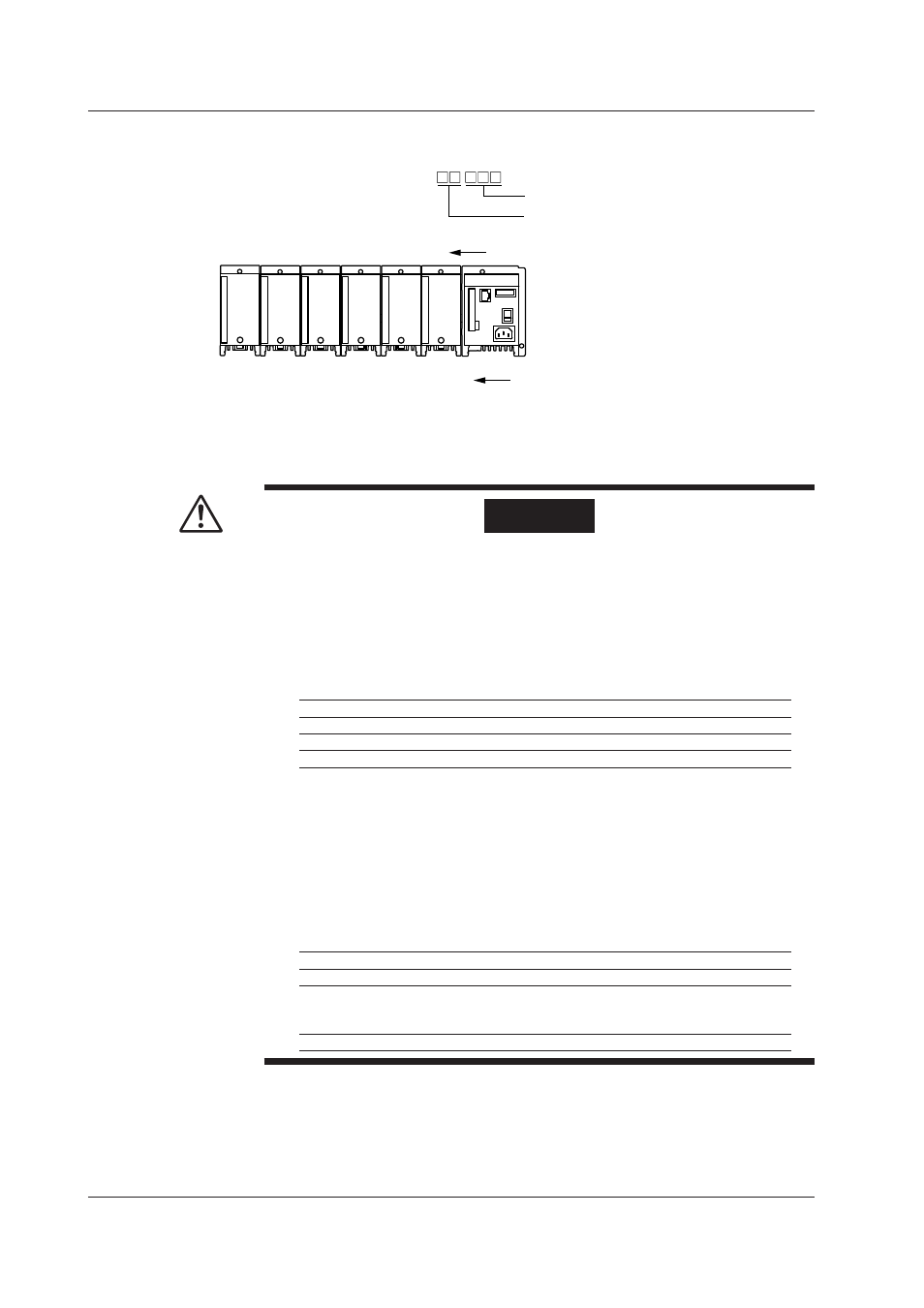
The figure below shows how the channel numbers are identified on the PC.
MX100
0
1
2
3
4
5
Slot number
001 to 010
011 to 020
021 to 030
031 to 040
041 to 050
051 to 060
Channel number in the unit
*2
Representation of channel numbers:
Channel numbers in a unit (001 to 060)
Unit number (00 to 89)
*1
*2 The last one digit on a 4-channel module is 1 to 4,
the last one digit on a 6-channel module is 1 to 6,
the last one digit on a 8-channel module is 1 to 8.
*1 Fixed to 00 when connecting using
the MX100 Standard software;
set between 00 and 19 when using
MXLOGGER software; and set
between 00 and 89 when using
the MW100 Viewer software.
General Precautions When Wiring the Input/Output Signal Wires
WARNING
• To prevent the possibility of electric shock when wiring, confirm that the
power supply source and the signal source are turned OFF. After making the
connections, secure the terminal cover and do not touch the terminals with your
hands.
• For signal wires on which voltage exceeding 30 VAC/60 VDC is applied relative
to the ground potential or between signals, use double (reinforced) insulation
wires. For all other signal wires, use basic insulation wires. For the withstand
voltage of insulation wires, see the table below.
Applied Voltage (Vrms or VDC) Basic Insulation Double (reinforced) Insulation
0 to 150
1350 Vrms
2700 Vrms
151 to 300
1500 Vrms
3000 Vrms
301 to 600
2210 Vrms
3700 Vrms
• To avoid electric shock when removing the screw terminal block and screw
terminal plate, be sure to attach the screw terminal block and screw terminal
plate to the input modules before inputting signals. Electric shock or fire can
result if signals are applied to the terminals when the screw terminal block or
screw terminal plate is removed from the input modules.
• When wiring to screw terminals, use round, insulation coated crimp-on lugs on
the terminals (4-mm screws on the screw terminal block, and 3-mm screws on
the screw terminals and screw terminal plate) that do not come out when loose.
• To prevent fire, use signal wires of the following temperature ratings.
Module Type
Temp. Rating
Screw terminal block
75°C
Universal input module, DCV/TC/DI input module, 4-wire RTD
resistance input module, Strain input module, Pulse input module,
Digital input module, Digital output module
80°C
Analog output module, PWM output module
85°C