Installation and connection instructions, Caution, Surface anchoring on a metal base – Alliance Laundry Systems WFF135 User Manual
Page 24: Directly on the ground
A
A
C
D
G
C
D
E
F
B
A
B
A
C
E
D
Label 1
Label 2
Label 3
24
4
Installation and Connection Instructions
The machine must be securely fixed on a flat surface (metal base,
concrete or solid ground). The anchoring is to be done on the
6 provided places (A) (See Label 1) in the holes on the corner of the
base. (See Mounting Bolt Hole Locations)
The machine must be placed entirely level. For easy maintenance it
is recommended to keep a minimal distance of 600 mm - 23.62 inch
between the wall and the back of the machine.
If several machines are placed next to each another, there should be a
minimal distance of 30 mm - 1.18 inch between each machine.
Surface
Anchoring on a metal base
The machine must be anchored directly on a concrete base. See
Label 3.
A: Bolt M12 (1/2”) (WFF65/75/100), M16 (5/8”) (WFF135/165)
B: Concrete base (WFF65/75/100: 25 cm - 9.48 inch, WFF135/165: 35 cm -
13.77 inch)
C: Washer 40x17x4 (1.57x0.60x0.15)
D: Nut M12 (1/2”) (WFF65/75/100), M16 (5/8”) (WFF135/165)
E: Base of the machine
IMPORTANT:
Machine bolts should be re-checked on a quarterly basis.
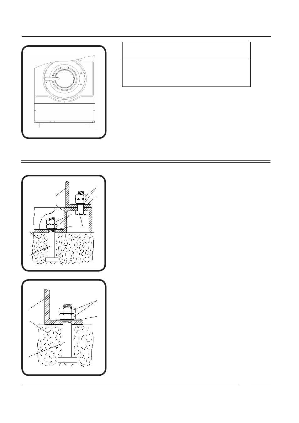
The machines must be fixed on a metal base which is securely
anchored on a concrete base. See Label 2.
WFF65/75/100 = WFF65, IWF065, IWF014, CWF065, CWF014, WFF75,
IWF074, IWF018, CWF074, CWF018, WFF100, IWF100,
IWF025, CWF100, CWF025
WFF135/165 = WFF135, IWF135, IWF030, CWF135, CWF030, WFF165,
IWF165, CWF165
A: Bolt M12 (1/2”) (WFF65/75/100), M16 (5/8”) (WFF135/165)
B: Concrete base (WFF65/75/100: 25 cm - 9.48 inch, WFF135/165: 35 cm -
13.77 inch)
C: Washer 40x17x4 (1.57x0.60x0.15)
D: Nut M12 (1/2”) (WFF65/75/100), M16 (5/8”) (WFF135/165)
E: Base of the machine
F: Metal base
G: Bolt M16x60 (5/8” x 2 1/2”)
Directly on the ground
CAUTION
Ensure that the machine is installed on a level floor of
sufficient strength and that the recommended clearances
for inspection and maintenance are provided. Never
allow the inspection and maintenance space to be
blocked.