Introduction, Specifications, 1 description – Yokogawa PR10 Retractable Assembly User Manual
Page 5: 2 features, 3 warranty, 1 general
5
IM 12B6K3-01E-E
1. INTRODUCTION
1.1 Description
The retractable fitting with ball valve allows
a safe insertion and retraction of a sensor
while the process is under pressure. It
can be mounted in a variety of positions.
The insertion depth can be selected on
site. An insertion stop is provided to set
the position of the sensor in the process.
The mechanism for releasing the probe
is designed to operate only when the ball
valve is closed, thus ensuring an effective
safety precaution and avoiding production
loss. The sensor can be replaced or
calibrated easily.
1.2 Features
• One model for pH, conductivity
and inductive conductivity sensors
• Integrated protection cage
• Build-in scraper to avoid contamination
of the fitting
• Usable for wide range of sensors
• A safe “through the valve” insertion
and retraction design
• Simplified installation by optional
ball valves with flanged or tapered
connections
• Optional flush port for keeping moist,
cleaning and calibration
• Available in Stainless Steel and with
Titanium shaft cage and adapters for
more harsh applications
1.3 Warranty
Yokogawa warrants that the goods
delivered are made from new materials to
the best workmanship available. Malfunction
of any of the delivered goods or parts of
it, can only lead to replacement of the
damaged parts. No claims can be made
to damages or accidents resulting from the
use of the goods. No claims can be made
to the expected or promised performance
of the goods under any circumstances.
Damaged goods or parts should be sent to
the local service organization for warranty
claim purposes. Yokogawa has the right to
deny warranty claims after investigation of
the data and materials.
2. SPECIFICATIONS
2.1 General
A. Wetted materials
- For sensor check Instruction Manual
- Stainless steel AISI 316L / Titanium
- O-ring seals: Viton 70° shore
B. Non-wetted materials
- For sensor check Instruction Manual
- Stainless steel AISI 316, 304
- Polypropylene glass filled
C. Insertion length
- Ref. mechanical drawing Fig. 2 - 5
on page 6 - 9.
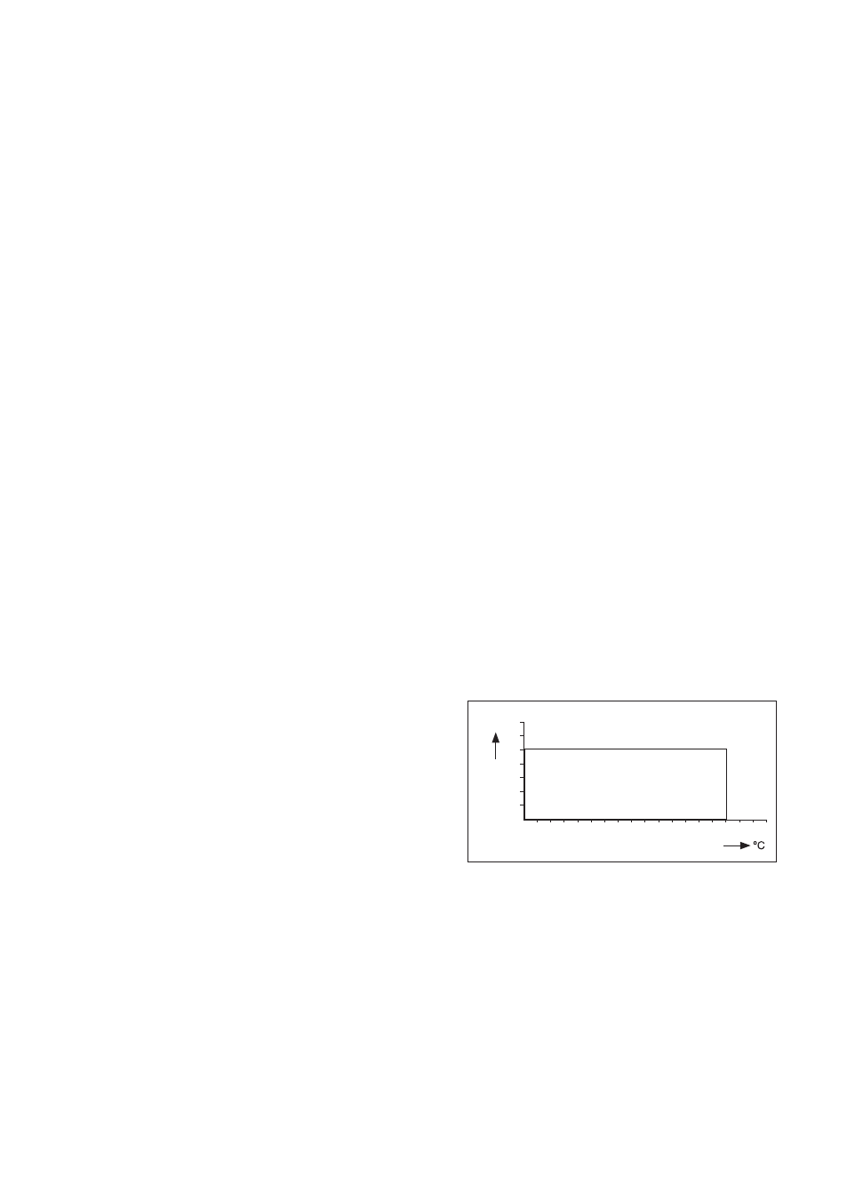
D. Pressure/temperature ratings
- Static conditions: see Fig. 1.
- Operating conditions during
extraction and insertion max.
500kPa, max. 100°C
E. Flange ratings:
- DIN flange DN32 PN10
- ANSI flange 1¼“ 150 lbs
- DIN flange DN50 PN10
- ANSI flange 2“ 150 lbs
F. Specifications of the sensor used
- Please check sensor specifications
G. Weight
- Approx 2.5 kg excl. ball valve
0 10 20 30 40 50 60 70 80
100
120
140
160
bar
2
4
6
8
10
12
AISI 316
FIG. 1 Pressure / Temperature graphic