7 output signal low cut mode setup, 8 integral indicator setup, Output signal low cut mode setup -19 – Yokogawa EJX210B User Manual
Page 54: Integral indicator setup -19
<8. Setting Parameters>
8-19
IM 01C27C01-01EN
8.3.7 Output Signal Low Cut Mode Setup
Low cut mode can be used to stabilize the output
signal near the zero point.
( There is 10% of hysteresis at only point of
transition from low to high)
[Setup Low Cut Value]
• Procedure to call up the Lower cutoff* display
AI1 block: Lower cutoff*
Example: setup LOW_CUT of output to 15%
Lower cutoff*
= (“Eu at 100%” - “Eu at 0%”) × 0.15 + “Eu at 0%”
*: “Low Cutoff” is used instead of “Lower cutoff” for
Detachable antenna type (Amplifier housing code: 8 or
9).
[Setup Low Cut Mode]
• Procedure to call up the Low Cut Mode display
AI1 block: Low Cut Mode
Example: Low cut at 20%
F0804.ai
(%)
50
20
0
50 (%)
For low cut in Linear mode
Example:
Low cut 20%
Input
Output
Output
For low cut in Zero mode
(%)
50
20
0
50 (%)
Example:
Low cut 20%
Input
Figure 8.2
Low Cut Mode
The low cut point has hysterisis so that the output
around the point is behaved as below figure.
Output mode: Linear
Low cut mode: Zero
Low cut: 20.00%
Output
Setting range:
0 to 20%
Input
0%
(20%)
2%
Low
cut
point
Hystrersis fixed at 10%
of the cut point
F0805.ai
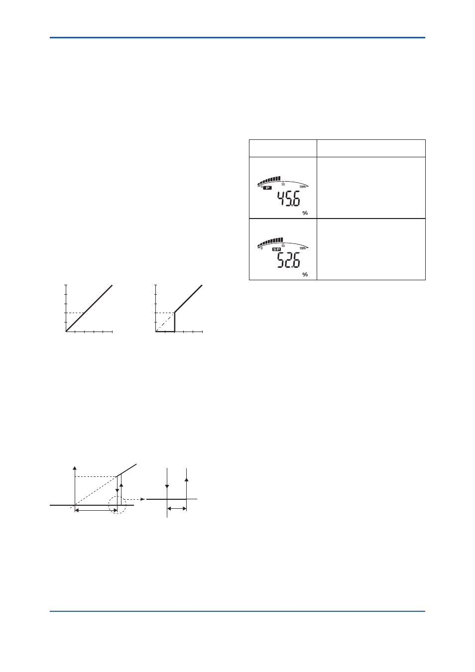
8.3.8 Integral Indicator Setup
The following three displays are available for
the Integral Indicator: differential pressure, static
pressure, and temperature.
The following three variables can be displayed on
the integral indicator: % of differential pressure
range, % of static pressure range, and % of
temperature range.
Available displays
Description
and related parameters
% of range
(PRES %)
Indicates input pressure in –10 to
110% range depending on the set
range (
LRV and URV).
PRES % 45.6 %
% of static pressure
(SP %)
*1
Indicates input static pressure in
–10 to 110% range depending on
the set range (
SP LRV and SP
URV).
SP % 52.6 %
*1:
Available for differential pressure transmitter.
Follow the procedure described in (1) to (2) below
to set the integral indicator.
(1) Display Selection
Display set to Display Selection is displayed on the
integral indicator.
• Procedure to call up the Display Selection
display
TRANSDUCER block: Display Selection
The Display Selection parameter enables the
differential pressure (AI1 block), static pressure
(AI2 block), and temperature (AI3 block) to be
displayed on the LCD. Select whether or not to
enable each block to be displayed.
(2) Cyclic Display
Information in the AI1 to AI3 blocks can be
displayed cyclically according to the display On/Off
setting for the differential pressure (AI1 block), static
pressure (AI2 block), and temperature (AI3 block)
selected in the Display Selection parameter.