Installation instructions: 1. installation, Wiring unit, Warning – Toxalert CM203 User Manual
Page 3: Caution, Figure 1
TOXALERT INTERNATIONAL, INC.,
P.O. BOX 159, MOUND, MINNESOTA 55364 (952) 472-4541 FAX (952) 472-4960
Visit our website at www. toxalert. com
INSTALLATION INSTRUCTIONS:
1. INSTALLATION:
Refer to Figure 1 and 2 to install and wire the
Toxalert monitor as follows:
1.) Locate a mounting location away from
direct fresh air intakes, and mount
vertically on wall or support column
approximately five to six feet above
floor.
2.) Open door and remove circuit board and
sensor from enclosure.
3.) Mount enclosure with hinge along left
side by using mounting holes (4 are
available).
4.) A wiring access hole must be added to
the enclosure anywhere along the bottom
or right side. Do not place an access hole
on the hinged side of the enclosure, since,
if conduit is used, this may restrict the
opening of the door. If conduit is to be
used, use a chassis punch to match the
required fitting size.
5.) Remove any metal chips and burrs from
enclosure.
6.) Reinstall the sensor and circuit board.
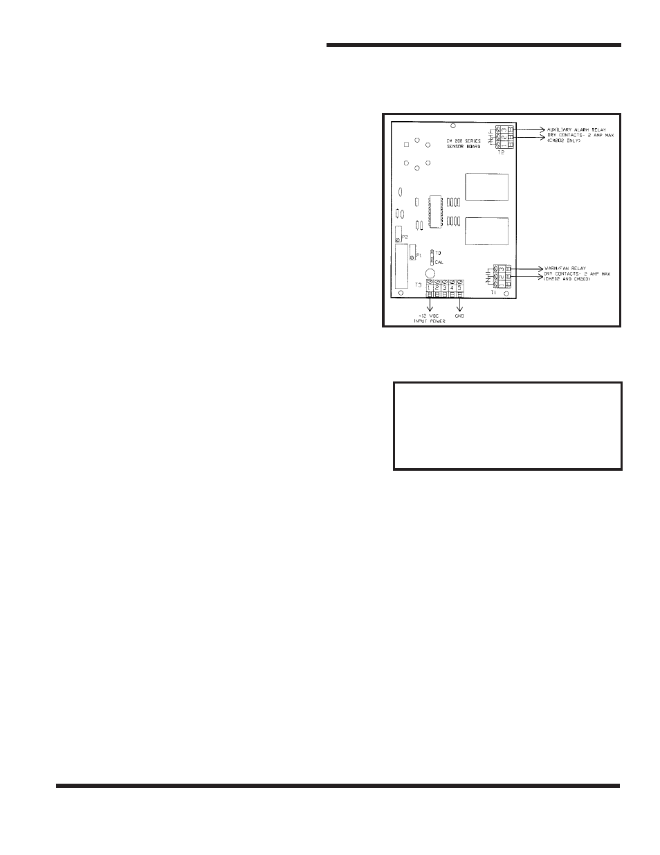
2. WIRING UNIT:
Refer to Figure 1
WARNING:
To prevent fire or shock
hazard turn off supply power and fan
power sources before making
connections. Comply with all local
building codes and ordinances.
1.) Connect power to T3 as follows:
T3-1 (+12VDC)
T3-5 (Ground)
2.) Model CM202 and CM203-Connect
control (i.e. fan) to R1 relay
contacts. Terminals T1-C (common)
and T1-NO (normally open) or T1-
NC (normally closed). Normally
open contacts T1-C and T1-NO
close on a rise in CO concentration
above fan on setpoint.
3.) Model CM202-Connect load (i.e.
remote alarm) to R2 relay contacts.
Terminals T2-C (common) and T2-
NO (normally open) or T2-NC
(normally closed).
4.) Turn on monitor power source, but
do not apply power to remote
devices at this time.
CAUTION:
Relays R1 and R2 are
rated for 2.0 amps resistive load. If a
higher rated load is being controlled,
add a remote relay between R1 or R2
and the load.
Figure 1
CM200 SERIES
CO CONTROL UNIT
Field Wiring Diagram