English – Pfister 023-CNFC/023-CNFCA User Manual
Page 4
4
English: Thank you for purchasing this Price Pfister
product. All Price Pfister products are carefully engineered,
and factory tested to provide long trouble-free use under
normal conditions. This product is easy to install using
basic tools and our easy to follow illustrated instructions.
If you have any questions regarding this product, see info
on previous page.
1 BEFORE PROCEEDING
WARNING: Read all the instructions completely before
proceeding. Price Pfister recommends calling a professional
if you are uncertain about installing this product!
This product should be installed in accordance with all local
and state plumbing and building codes.
2 SHUT OFF WATER SUPPLY
Locate water supply inlets and shut off the water supply
valves. These are usually found under the sink or near the
water meter. If you are replacing an existing Bidet, remove
the old Bidet from the sink and clean the sink surface
thoroughly.
3 ASSEMBLY INSTRUCTIONS
If operating pressures exceed 5 BAR (75 PSI), the use of
a pressure reducer is recommended. Before proceeding
with the assembling, we advise to clean the hot and cold
water tubes, in order to avoid build-up of dirt that could
compromise the functioning of the Bidet.
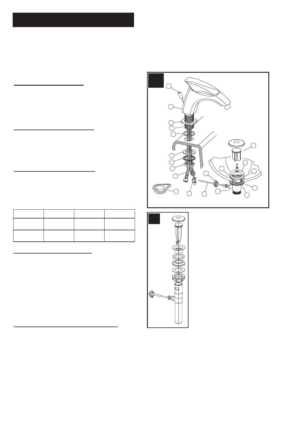
4 INSTALLING BIDET (Fig.A)
Insert Lift Rod (1) into hole at the back of Bidet Body (2).
Ensure that Seal Base (5) is pressed onto Spout Base (4).
Place Spout Base (4) and Seal Base (5) onto the bottom of
Bidet Body (2). From above sink, insert Bidet Supply Tubes
(9) and Threaded Shank (3) through Hole on the sink.
From underneath sink, secure Bidet Body (2) by placing
Rubber Washer (6), Metal Washer (7) and threading Nut
(8) onto Threaded Shank (3). For thin decks use Flange
(20) instead of Washers (6 & 7) to secure Bidet.
Caution: Do not over tighten!
5 DRAIN BODY INSTALLATION (Fig.A)
The Flange (17) can be installed with or without Rubber
Seal (10). If Drain Flange (17) is installed without Rubber
Seal, Apply a small bead of plumber’s putty underneath
the Drain Flange (17) and around Drain Opening (18).
Insert Drain Flange (17) into Drain Opening (18). From
underneath, slide Rubber Washer (11) onto the bottom
of Drain Flange (17). Thread Locknut (12) until Rubber
Washer (11) seats securely inside Drain Opening (18).
Remove excess plumber’s putty. Adjust Drain Body so
that the Ball Rod Opening (15) faces the rear.
Supply
Suggested
Maximum
Minimum
Hot Water
Temperature
65 Cº (150ºF)
80 Cº (175ºF)
15 Cº (60ºF)
Operating
Pressure
3 BAR (44PSI)
5 BAR (73PSI)
0.5 BAR (7PSI)
ENGLISH
Drop Stopper (16) into Flange (17). Place Nut (19) onto
Ball Rod (13). Insert the Ball Rod (13) into the Ball Rod
Opening (15) through the Stopper Hole (16) and secure
with Nut (19). Place one end of Spring Clip (14) onto the
end of Ball Rod (13). Insert Ball Rod (13) into Clip (14).
Be sure to leave enough space between Lift Rod (13) and
Spout Body (2) when Lift Rod is down. NOTE: Your model
may have an alternate drain body assembly (see fig. A2).
2
1
4
3
5
6
7
8
9
20
16
11
12
15
18
19
10
17
13
14
A
A2