Rs-422a, Rs-422a interface pinouts, Rs-422 interface wiring – Watlow Series 945 Data Communications User Manual
Page 4
How to Use Data Communications
4
WATLOW Series 945
19
20
21
22
23
T +
T -
R +
R -
Signal Common
(Optional)
Series 945 #1
Series 945 #10
Twisted Pair Wire
1
2
3
4
5
9
8
7
6
19
20
21
22
23
T +
T -
R +
R -
Signal Common
(Optional)
Twisted Pair Wire
T +
T -
R +
R -
Com
Host Computer
(rear view)
DB-9 female
connector
(viewed from wire side)
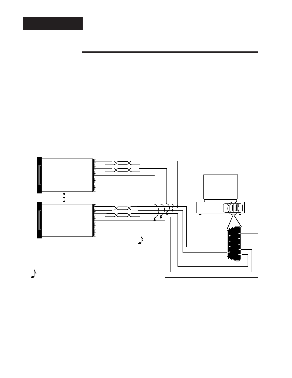
RS-422A
RS-422A Interface Pinouts
945A-XXXX-B000
The RS-422A communications uses a four wire (full duplex) system. There are
two separate lines for transmitting, and two lines for receiving data between the
computer and the Series 945. With RS-422A you can have from one to ten Series
945 controls connected to a single computer.
This diagram is a typical wiring example. The connections on the host computer
may vary depending on models. Refer to your computer user's manual for more
information.
Figure 1 -
RS-422A Interface,
Pin Designations.
NOTE:
The Electronic
Industry Association
(EIA) RS-422A
standard recom-
mends a maximum
4000 ft. total network
distance.
- 12LS Controller (111 pages)
- 8LS Controller (140 pages)
- 8PID Controller (55 pages)
- Addendum to EZwarePlus (50 pages)
- ANASCAN (62 pages)
- ANASOFT (95 pages)
- ANAWIN 2 (154 pages)
- ANAWIN 3 (23 pages)
- Calibrating Watlow Series 988 Family Process Controls (19 pages)
- CAS (98 pages)
- CAS200 (124 pages)
- CLS (180 pages)
- CLS200 (251 pages)
- CLS200, MLS300 and CAS200 (92 pages)
- Control Console (12 pages)
- CPC400 (230 pages)
- DIN-A-MITE Style A (9 pages)
- DIN-A-MITE Style B (14 pages)
- DIN-A-MITE Style C (22 pages)
- DIN-A-MITE Style D (9 pages)
- DIN-Mount Adapter Instruction Sheet, Rev A (1 page)
- Dual DAC (4 pages)
- EM Gateway (28 pages)
- E-Safe Hybrid Relay Rev B (4 pages)
- E-SAFE II Hybrid Power Switch (4 pages)
- EZwarePlus Programming (264 pages)
- EZ-ZONE PM (111 pages)
- EZ-ZONE PM PID (125 pages)
- EZ-ZONE PM Express Limit (34 pages)
- EZ-ZONE PM Express (35 pages)
- EZ-ZONE PM Integrated Controller (181 pages)
- EZ-ZONE RM Limit Module Rev C (127 pages)
- EZ-ZONE RMA Modul (79 pages)
- EZ-ZONE RMC (236 pages)
- EZ-ZONE RME (124 pages)
- EZ-ZONE RMH (161 pages)
- EZ-ZONE RUI/Gateway (62 pages)
- EZ-ZONE RM-Scanner-Modul (140 pages)
- EZ-ZONE ST (97 pages)
- F4 External Event Board - Rev.B (2 pages)
- HG Series Mercury Displacement Relay (6 pages)
- LogicPro (296 pages)
- Mercury Relay or MDR Retrofit (13 pages)
- MICRODIN (106 pages)
- MICRODIN (24 pages)