Wire output, Output wiring, Figure 22 – Watlow Series 922 Retrofit User Manual
Page 40: Solid state switch, option "cc", wiring diagram, Figure 23, Figure 24
32
WATLOW Series 922 User's Manual
How to Install and Wire, Chapter 4
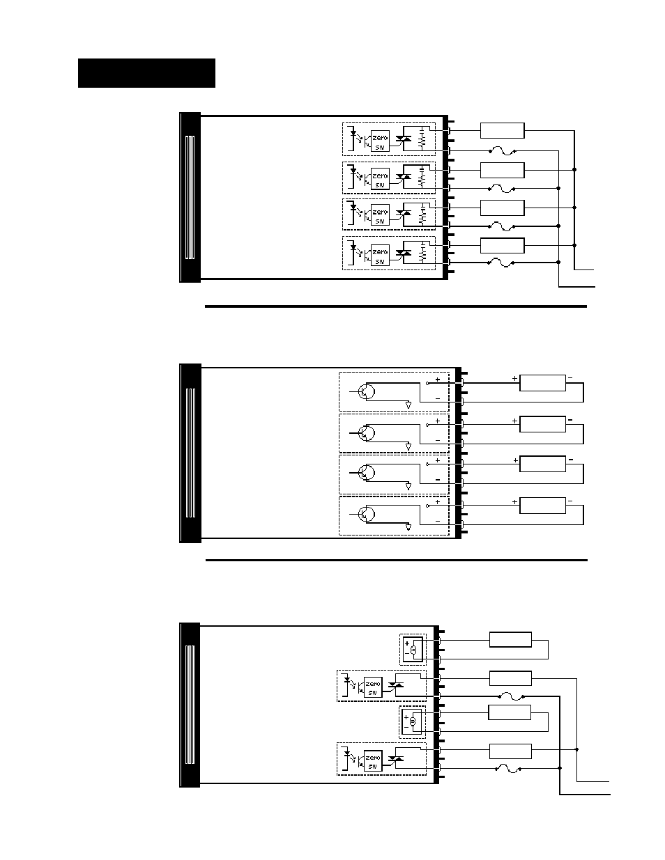
Wire Output
Figure 22 -
Dual S.S. Relay
Output, Option
"BB", Wiring
Diagram.
Figure 23 -
Solid State Switch,
Option "CC", Wiring
Diagram.
Figure 24 -
4-20mA/Solid State
Output, Option
"FB", Wiring
Diagram.
LOAD
LOAD
LOAD
LOAD
Output 1
Output 3
Output 4
10
11
9
12
13
14
15
16
Output 2
Output 1
Output 2
Output 3
Output 4
20mA Max
15
20VDC
20mA Max
13
20VDC
20VDC
11
20mA Max
9
20mA Max
10
12
14
16
-
+
11
Output 1
Output 2
Output 3
Output 4
-
4-20mA
600 Max
LOAD
-
+
600 Max
LOAD
9
10
12
13
14
15
16
Fuse
4-20mA
Fuse
Output Option "BB", Dual Solid State Relay
Model # 922A -
_ BB
_ - _ 000
Output Option "CC", Solid State Switch
Model # 922A - _
CC
_ - _ 000
Output Option "FB", 4-20mA/ Solid State
Model # 922A - _
FB
0 - _ 000
NOTE: If
SPCLFUNC
parameters OUT 1
and/or OUT2 are
set to CL HT, then
Outputs1 and/or 3
will be the cooling
output and
Outputs 2 and/or
4 will be the
heating outputs.
Channel 1
Channel 2
Channel 1
Channel 2
Channel 1
Channel 2
L2 (Neutral)
L1 (Hot)
L2
L1
20VDC