Wiring, Displays, Power wiring – Watlow Series 321 User Manual
Page 4: Output 1 wiring output 2 wiring interlock wiring, Point ➀ is flashing, Points ② and ➂ are not illuminated, Points ② and ➂ are illuminated, Numeric display is illuminated, L1 l2 fuse, Cno 1
WATLOW Series 321 User's Manual
4
Wiring
Ó
WARNING:
Possibility of
shock. There
is no isolation.
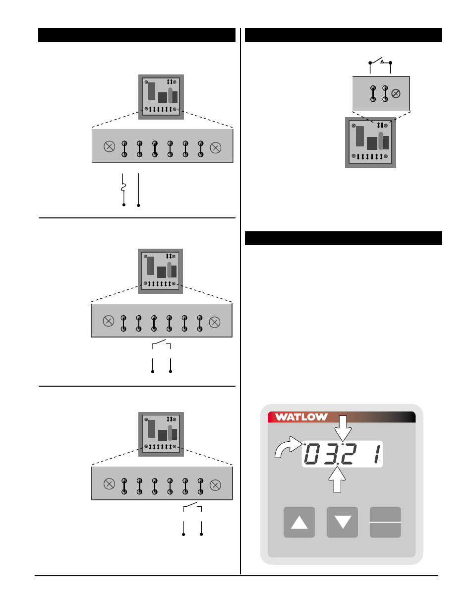
Power Wiring
Voltage Input: 120V~ (ac), nominal.
Output 1 Wiring
Output 2 Wiring
Interlock Wiring
Figure 4a –
Series 321
back view.
Figure 4b –
Series 321
back view.
Figure 4c –
Series 321
back view.
Figure 4d –
Series 321
back view.
ç
NOTE: The switch and
wiring practices used
for interlock operations
must meet U.L. Stan-
dards.
NOTE: The Interlock
must be closed for the
timer to initiate a
timing sequence.
ç
L1
L2
C
NO
C
NO
AC
1
2
L1 L2
Fuse
IL
L1
L2
C
NO
C
NO
AC
1
2
C
NO
1
L1
L2
C
NO
C
NO
AC
1
2
IL
L1
L2
C
NO
C
NO
AC
1
2
C
NO
2
L1
L2
C
NO
C
NO
AC
1
2
IL
L1
L2
C
NO
C
NO
AC
1
2
IL
L1
L2
C
NO
C
NO
AC
1
2
IL
IL
Displays
Figure 4e – Series 321 front display.
• Point ➀ is flashing:
Interlock is in an open condition, see
Figure 4e.
• Points ② and ➂ are not illuminated:
Timer is in a Hold/Ready condition, see
Figure 4e.
• Points ② and ➂ are illuminated:
Timer is running, see Figure 4e.
• Numeric Display is illuminated:
The Numeric Display is always active
when power is applied to the timer, see
Figure 4e.
Wiring
Stop
Start
Time Set
321
➀
➁
➂