Installation – Watlow Series 321 User Manual
Page 2
WATLOW Series 321 User's Manual
2
Through-the-Panel Installation Procedure:
1. Make a panel cutout using the dimensions in
Figure 2c.
2. Remove the timer from its collar and set the
collar aside.
3. Insert the timer into the cutout. Check to see
that the gasket is not twisted and is fully seated
in its channel.
Installation
Dimensions
Dimensions
2.585" (65.7mm)
Mounting
Collar
321 Timer Front Panel
1.750"
(44.5mm)
3.325"
(85.46mm)
2.585" (65.7mm)
Mounting
Collar
321 Timer Front Panel
1.750"
(44.5mm)
3.325"
(85.46mm)
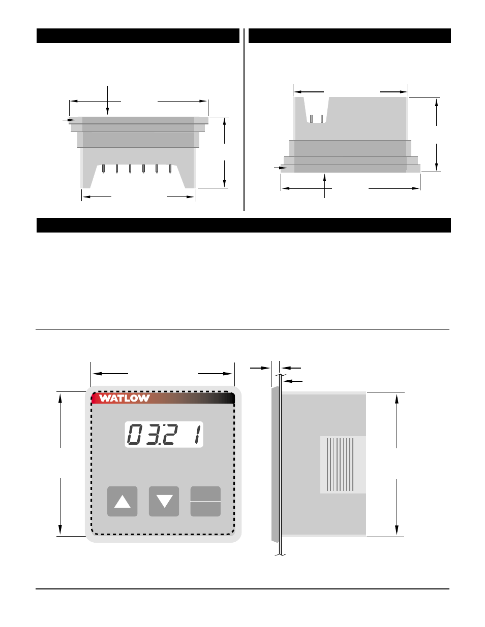
Figure 2a – Series 321 Timer inserted
in the mounting collar, bottom view.
Figure 2b – Series 321 Timer inserted
in the mounting collar, top view.
4. While pressing the front of the timer against the
panel, slide the mounting collar over the back of
it. The tabs on the collar must line up with the
ridges on the timer for secure installation - see
Figure 1b.
5. The tabs on each side of the collar have teeth
that latch into the ridges of the timer. Be sure
to apply enough pressure to firmly install the
timer.
Figure 2c – Series 321 Through-the-Panel dimensions.
Stop
Start
Time Set
321
2.585" Square Cut
(65.7mm)
2.585" (65.7mm)
2.585"
(65.7mm)
.250" (6.35mm)
Panel