Power wiring, Input wiring, Output wiring – Watlow Series 145 User Manual
Page 3: Safety information
3
■
Watlow Series 145 User’s Manual
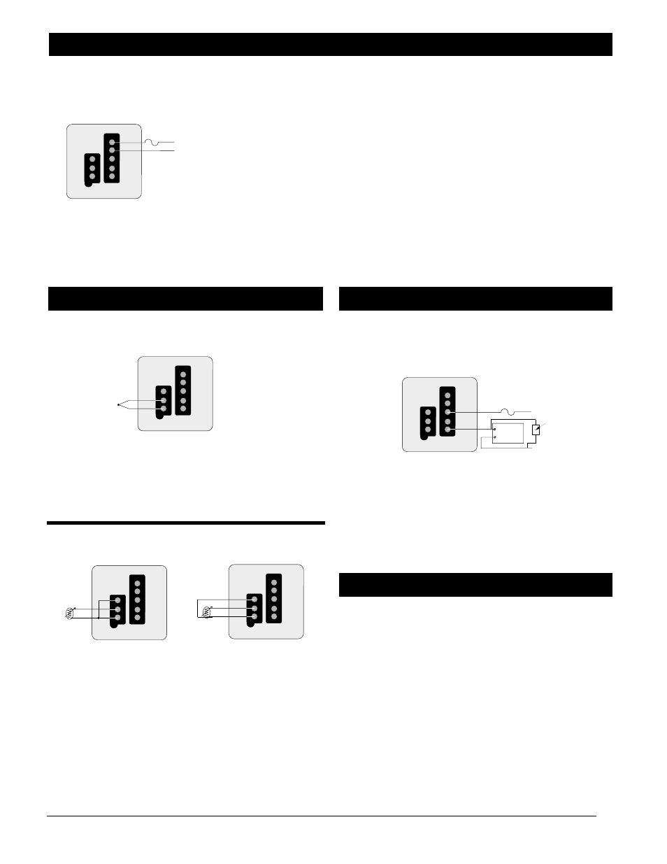
Power Wiring
Thermocouple
Figure 3b — Thermocouple wiring.
NOTE: When an external device with a non-isolated circuit common
is connected to the dc output, you must use an isolated or unground-
ed thermocouple.
2- and 3-Wire RTD
Figure 3c — 2- and 3-wire RTD wiring.
NOTE: Using 2- or 3-wire RTD input, platinum 100
Ω
, 500
Ω
, or
1000
Ω
at 0°C calibrated for DIN 0.003850
Ω
/
Ω
°C curve.
Electromechanical Relay, 3A, Form C with suppression
145D - _ _ _ _ - 0000
Figure 3d — Electromechanical relay wiring.
NOTE: No external reset wiring is available.
Note, caution and warning symbols appear throughout this
book to draw your attention to important operational and
safety information.
A “NOTE” marks a short message to alert you to an
important detail.
A “CAUTION” safety alert appears with information that is
important for protecting your equipment and performance.
A “WARNING” safety alert appears with information that is
important for protecting you, others and equipment from
damage. Pay very close attention to all warnings that apply
to your application.
The ç symbol (an exclamation point in a triangle) precedes
a general CAUTION or WARNING statement.
The Ó symbol (a lightning bolt in a lightning bolt in a
triangle) precedes an electric shock hazard CAUTION or
WARNING safety statement.
Safety Information
ç
NOTE: Switching inductive loads (relay coils, solenoids, etc.)
with the mechanical relay, switched dc or solid-state relay output
options requires use of an R.C. Suppressor. Watlow carries the
R.C. suppressor Quencharc brand name, which is a trademark of
ITW Paktron. Watlow Part No. 0804-0147-0000.
Fuse
L1
L2
External
Device
C
NC
NO
S
e
n
s
o
r
1
2
3
4
5
Customer
Supplied
Quencharc
Output Wiring
S1
S3
S2
S
e
n
s
o
r
1
2
3
4
5
3-Wire RTD
S1
S3
S2
S
e
n
s
o
r
1
2
3
4
5
2-Wire RTD
S
e
n
s
o
r
1
2
3
4
5
TC-
TC+
Input Wiring
120VÅ
145 _ - 1 _ _ _ - 0000
230 to 240 VÅ
145 _ - 2 _ _ _ - 0000
NOTE: The line voltage is specified by your model number.
Figure 3a — Power wiring.
Ó
CAUTION Applying incorrect voltage may result in irreversible
damage to the controller.
Ó
WARNING: To avoid potential electric shock, use National Electrical
Code (NEC) safety practices when wiring and connecting this unit to
a power source and to electrical sensors or peripheral devices.
Failure to do so could result in injury and death.
All wiring and fusing must conform to the National Electric
Code and to any locally applicable codes.
ç
WARNING: The Series 145 Temperature Limit Switch should be
mounted in an inconspicuous location to discourage unauthorized
changes to the set point. Only approved personnel should have the
authority to change the set point on the limit switch. Failure to
comply with these recommendations could result in damage to
equipment and property, and injury to personnel.
S
e
n
s
o
r
Recommended fuse size: 1A
Fuse
L1
L2
1
2
3
4
5