Dimensions, Wiring guidelines, Installation – Watlow Series 145 User Manual
Page 2: User interface, Installation wiring guidelines
2
■
Watlow Series 145 User’s Manual
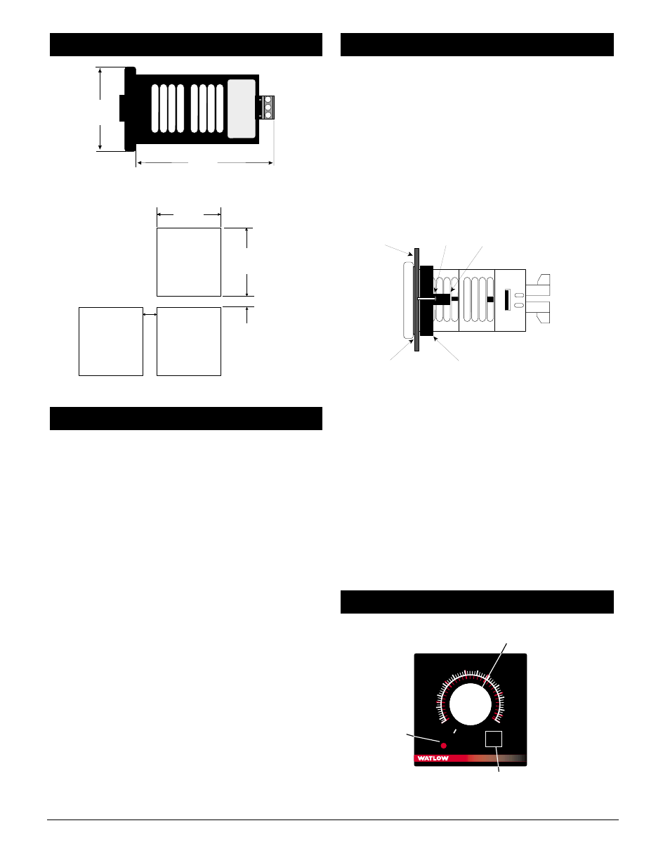
Figure 2a — Series 145 dimensions.
Figure 2b — Series 145 panel cutout.
• Use the correct sensor type per the model number on the
unit sticker.
• Use the proper thermocouple or RTD polarity.
• Insulate the thermocouple mounting from the mounting
surface to prevent heat migration input errors.
• Thermocouple leads should be twisted pair wire and
routed separately from any other lines.
• In electrically noisy environments (heavy switching of
contactor, motors, solenoids, etc.) use shielded thermocou-
ple lead wire with the shield connected at the sensor end
only.
• All wiring and fusing must conform to the National
Electric Code (NEC) NFPA70 and any other locally appli-
cable codes.
• Fuse the independent load voltage on the L1 (hot) side
and connect it to the common (COM) side of the relay.
ç
CAUTION: A power disconnect switch located near the controller
is recommended to shut down power in case of controller
failure.
• Long lead lengths create electrical resistance. When using
a two-wire RTD, there will be an additional error for
every 1
Ω
of lead length resistance. That resistance when
added to the resistance of the RTD element, can result in
erroneous input to the temperature controller. To over-
come this problem, use a three-wire RTD sensor, which
compensates for lead length resistance. When extension
wire is used for a three-wire RTD, all three extension
wires must have the same electrical resistance (i.e. same
gauge, copper stranded).
To Mount the Series 145
1. Make a panel cutout, using the dimensions in Figure 2b.
2. Check to see that the external case gasket of the Series
145 is facing the panel surface. Insure that the gasket is
not twisted and is seated within the case bezel flush with
the bezel. Insert the Series 145 into the cutout.
3. Slide the mounting collar over the back of the controller.
The two tabs of the mounting collar will fit into one of the
vent openings of the case.
4. While pressing the front of the case firmly against the
panel, tighten the two #8-32 screws until tight. Make sure
you cannot move the case within the cutout.
Figure 2c — Series 145 mounting.
NOTE: FM Approval requires limit switches to be suitably enclosed
to minimize casual readjustment of set temperature.
To Remove the Series 145
1. Remove the Series 145 by loosening the mounting screws
located on the mounting collar.
2. Using the screws, gently pry them away from the case.
This will lift the mounting tabs, allowing the collar to
slide backwards.
NOTE: To guarantee a proper seal, make sure the gasket between
the panel and the rim of the case is not twisted and is seated prop-
erly. Press firmly.
NOTE: Make sure the rounded side of the D-shaped external case
gasket faces the panel surface and the gasket is fully seated.
Figure 2d — Series 145 interface.
RESET
˚C
˚F
Alarm
145
100
150
200
250
300
350
400
450
500
550
600
50
0
50
150
200
100
250
300
315
Type J T/C
Alarm
Indicator
Temperature Adjustment
Setpot
Reset
User Interface
Panel
Screw
Mounting Tab
External Gasket
Mounting Collar
Installation
Wiring Guidelines
2.10"
1.75"
Panel Cutout
Your Panel
Thickness
0.06 to 0.38 in
(1.5 to 9.7 mm)
1.77 to 1.79 in
(45.0 to
45.5 mm)
1.77 to 1.79 in
(45.0 to
45.5 mm)
0.38 in
(9.7 mm)
Minimum
0.85 in
(20 mm)
2.1 in
(55 mm)
square
4.0 in
(102 mm)
Dimensions