Wiring guidelines, Power wiring, Input wiring – Watlow Series 101 User Manual
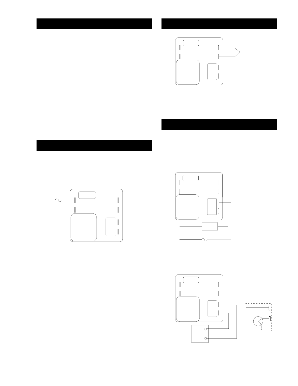
Page 3: Output wiring, Power wiring wiring guidelines
Watlow Series 101 User’s Manual
■
3
• Use the correct thermocouple type matching the model
number on the unit sticker. See the underside of the
unit.
• Use the proper thermocouple polarity. Red is negative.
• Insulate the thermocouple mounting from the mounting
surface to prevent heat migration input errors.
• Thermocouple leads should be twisted pair wire and
routed separately from any other lines.
• In electrically noisy environments (heavy switching of
contactor, motors, solenoids, etc.) use shielded thermo-
couple lead wire with the shield connected at the sensor
end only.
• All wiring and fusing must conform to the National
Electric Code (NEC) NFPA70 and any other locally
applicable codes.
• Fuse the independent load voltage on the L1 (hot) side
and connect it to the common (COM) side of the relay.
120VÅ
101 _ - 1 _ _ _ - 0000
230VÅ
101 _ - 2 _ _ _ - 0000
24VÅ
101 _ - 3 _ _ _ - 0000
NOTE: The line voltage is specified by your model number.
Figure 3a — Power wiring.
Ó
WARNING: To avoid potential electric shock, use National
Electrical Code safety practices when wiring and connecting this
unit to a power source and to electrical sensors or peripheral
devices.
All wiring and fusing must conform to the National Electric Code
and to any locally applicable codes.
Ó
WARNING: Applying incorrect voltage may result in irreversible
damage to the control.
NOTE: We strongly recommend that all control loops use an
approved temperature limit control for over or under temperature
limit protection. Failure to install temperature limit control pro-
tection where a potential hazard exists could result in damage to
equipment and property and injury to personnel.
Figure 3b — Thermocouple wiring.
NOTE: When an external device with a non-isolated circuit com-
mon is connected to the dc output, you must use an isolated or
ungrounded thermocouple.
Electromechanical Relay, Form C with suppression 3A
101A - _ _ _ _ - 0000
Solid State Relay, Form A, 0.5A without suppression
101B - _ _ _ _ - 0000
Figure 3c — Mechanical and solid-state relay wiring.
Switched DC
10 1C - _ _ _ _ - 0000
Figure 3d — Switched dc wiring.
dc+
dc-
External
Device
dc-
dc+
18V
Î
(dc)+
dc-
Internal Circuitry
Fuse
L1
L2
External
Device
+
tc
-
tc
Fuse
L1
L2
L1
L2