Ordering information, Safety, Installation – Watlow Series 101 User Manual
Page 2: Dimensions
Watlow Series 101 User’s Manual
■
2
(1576)
101 _ - _ _ _ _ - 0000
Output
A = Electromechanical relay,
Form A, 3A, with contact
suppression
B = Solid-state relay, 0.5A, Form A,
without contact suppression
C = Switched dc, non-isolated
Line Voltage
1 = 120V
Å
2 = 230V
Å
3 = 24V
Å
Input and Range
Type J
601 = -20 to 260°C
(0 to 500°F)
602 = -20 to 540°C
(0 to 1000°F)
608 = -20 to 120°C
(0 to 250°F)
Type K
603 = -20 to 1100°C (0 to 2000°F)
Note: User documentation may be available in French, German, Spanish,
Italian, and Dutch, as well as English. Check Watlow’s website
(www.watlow.com/) for availability. Specify language at time of order.
ç
A Caution symbol (an exclamation point in a triangle) appears with
information that is important to protect equipment and perfor-
mance. Read and follow all cautions that apply to your application.
The equipment is protected throughout by double or reinforced
insulation. Use only to Watlow specifications. If the Series 101 is
used in a manner not specified by Watlow, the protection provid-
ed by the equipment may be impaired.
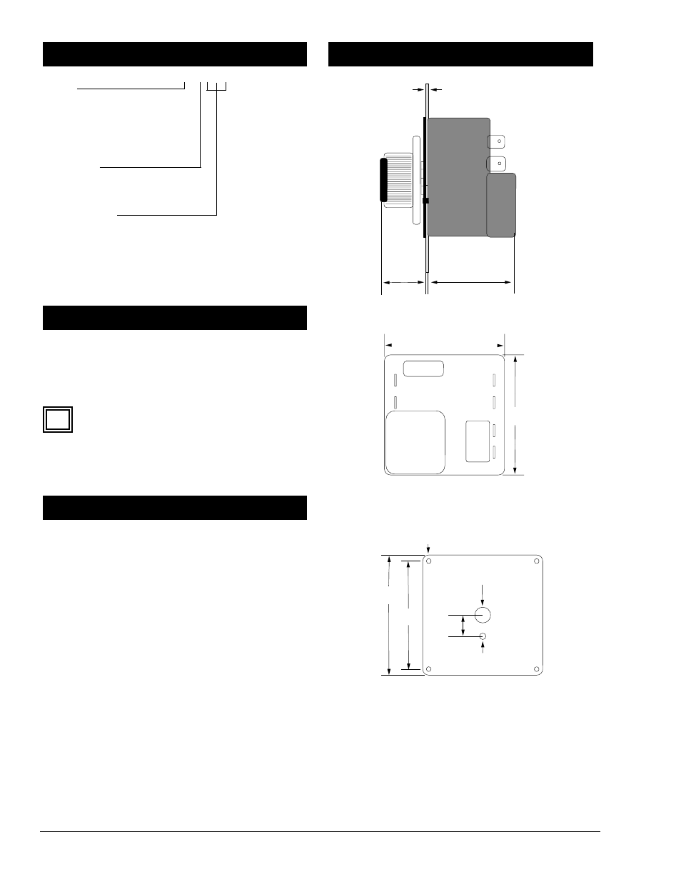
1. Remove the setpot knob and the dial scale from the
Series 101 control. See the side view in Figure 2a.
2. Using the dial scale as a location/drilling template,
locate and center punch the setpot locating tab, setpot
shaft and four mounting holes at the desired location.
See Figure 2c.
3. Drill one 4 mm (0.156 in.) setpot locating tab hole, one
10.3 mm (0.406 in.) setpot shaft hole and four 3.2 mm
(0.128 in.) diameter mounting holes.
4. Insert the setpot shaft of the controller through the 10.3
mm (0.4064 in.) diameter hole. Replace the dial scale
and align the mounting holes, then tighten the pot
shaft nut.
5. Insert #4 thread-forming screws in mounting holes and
tighten in place.
6. Wire the control following the wiring diagrams. See
next page.
NOTE: The Series 101 has a 2.3 mm (0.090 in.) diameter by 13
mm (0.500 in.) deep screw hole cavity. Design is based on using
Textron Camcar Division “Plastite” or “Pushtite” thread forming
hardware or equivalent. Screw length is 9.5 to 12.7 mm (0.375 to
0.500 in.) maximum.
Figure 2a — Series 101 side dimensions.
Figure 2b — Series 101 dimensions.
Figure 2c — Series 101 mounting.
setpot shaft hole,
9.9 mm (0.39 in.) diameter
Setpot locating tab hole,
3.6 mm (0.140 in.) diameter
Mounting hole, (4) 3.1 mm (0.120 in.)
diameter for #4 thread-forming screws.
NOTE: Screw length ranges from 9.5 mm
(0.375 in.) to 12.7 mm (0.500 in.) maximum.
13.5 mm
(0.53 in.)
56.6 mm
(2.70 in.)
75.2 mm
(3.00 in.)
75.2 mm
(3.00 in.)
75.2 mm
(3.00 in.)
27.9 mm
(1.10 in.)
54.1 mm
(2.13 in.)
2.3 mm (0.09 in.) maximum
panel thickness