Atlantis Land 10/100Mbps User Manual
Page 28
22
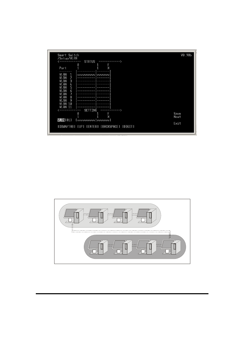
Figure 14. VLAN Configuration
For example, there are five computers (PC1~PC5) connected to
the Switch’s port 1~5. They had been divided into two VLAN
groups: VLAN1 (PC1~PC4) and VLAN2 (PC2~PC5). There is
no way to connect PC1 and PC5 shown as Figure 15. If PC1 has
to connect to PC5, it should joint PC1 and PC5 in the same
VLAN.
1
2
3
4
VLAN1
5
2
3
4
VLAN2
X
Figure 15. There is no connection between PC1 and PC5
Using VLAN, it can divide the Switch into many independent
small switches. For example, in Figure 16, the Switch has been
See also other documents in the category Atlantis Land Hardware:
- I-Storm USB ADSL modem A01-AU2 (83 pages)
- A02-SG32 (2 pages)
- A02-UP-W108 (87 pages)
- A07-VG3318 (2 pages)
- A02-RA242-W54 (84 pages)
- 32 bit 10/100 Fast Ethernet Card A02-S32-S (2 pages)
- DiskMaster HDE 103 (2 pages)
- 56K V.90/V.92 (20 pages)
- A02-RA340 (81 pages)
- A02-UP-W54 (75 pages)
- I-FLY A02-WAP-54G (9 pages)
- A02-RA242-W54_GX01 (80 pages)
- 111U (98 pages)
- Wireless 54Mbps USB Adapter 6440 A02-UP-W54 (89 pages)
- Mistral Terminal Adapter 128Kbps ATLM (2 pages)
- DiskMaster A06-HDE102 (2 pages)
- A02-RA3 (3 pages)
- I-FLY A02-WR-54G2 (13 pages)
- A07-VES3302-36 (2 pages)
- A02-WS2 GX01 (77 pages)
- WebRunner PCI V.90/V.92 56K Modem A01-PP3R (2 pages)
- A02-WS1 GX01 (92 pages)
- A02-PL100 (58 pages)
- I-Storm USB ADSL Modem A01-AU1 (61 pages)
- A02-RB-W54 (22 pages)
- I-Fly PCMCIA Wireless Card A02-WPCM-54G (2 pages)
- NetFly Wireless USB Adapter USB 54 (24 pages)
- I-Storm (30 pages)
- A02-AP-W54 (12 pages)
- WebShare 241 ROUTER ADSL2+ A02-RA241 (82 pages)
- A01-AU3 (2 pages)
- A02-AP2-W54M_MS01 (60 pages)
- I-Fly PCMCIA Wireless Card A02-WPCM-11B (2 pages)
- NETFLY PCI 54 (31 pages)
- A02-RA243-W54M (88 pages)
- WebShare 144WN (4 pages)
- A07-WA6202 (2 pages)
- AP1-54 (64 pages)
- A02-WAP-54G (49 pages)
- Web Runner 56K V.92 (13 pages)
- A02-RA141-W54 (96 pages)
- A02-S32-S/M2 (9 pages)
- WEBRUNNER USB A01-PU2 (35 pages)
- U-108 (8 pages)