Fc8001, Block diagram, Rf tuner – Silicon Motion FC8001 User Manual
Page 7
ⓒ
Copyright 2008 FCI (All Rights Reserved)
Product datasheet 7/49 Rev. 18 Feb. 2009
-
FC8001
Terrestrial Digital Multimedia Broadcast
RF tuner & Demodulator
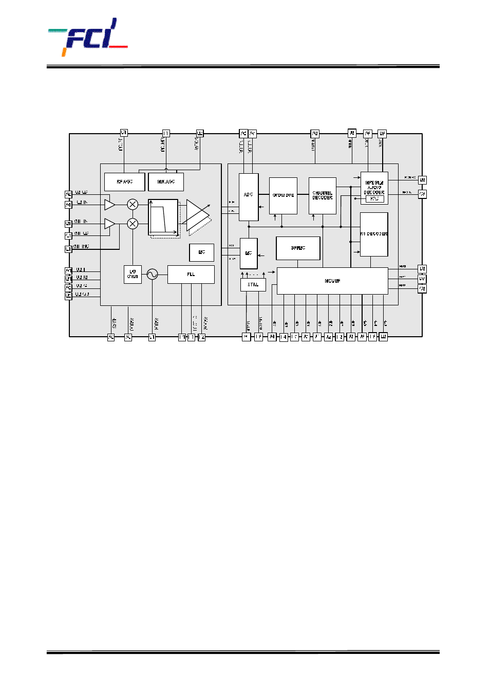
1.3. Block Diagram
Figure 1. T-DMB Block Diagram
1.4. RF Tuner
RF tuner has a direct-conversion structure that converts Band-3 or L-Band signal around DC
frequency. RF AGC and MIX AGC are controlled by the on-chip demodulator, and they regulate signal
level to a proper value for the internal tuner blocks. The on-chip demodulator controls the gain of
the PGA (Programmable Gain Amplifier), and PGA supply uniform signal to ADC as a result. A low
noise fractional-N type frequency synthesizer and a VCO are integrated for generating LO(Local
Oscillator) signal to direct-conversion.