L-o-x, Accessories, Muffl-air – Ross Controls MODULAR MANUAL User Manual
Page 2: Silencer, Warranty and cautions, Ross controls, Odular, Ntry, Ackages, Xamples modular l-o-x
Printed in the U.S.A. – Rev. 07/12
© 2012,
ROSS CONTROLS
®
. All Rights Reserved.
Form NPS033
ACCESSORIES
WARRANTY and CAUTIONS
Standard ROSS warranty and cautions apply, available upon request or at www.rosscontrols.com.
ROSS EUROPA GmbH
Germany
Fax: 49-6103-74694
ROSS ASIA K.K.
Japan
Fax: 81-427-78-7256
ROSS UK Ltd.
United Kingdom
Fax: 44-121-559-5309
ROSS SOUTH AMERICA Ltda.
Brazil
Fax: 55-11-4335-3888
ROSS CONTROLS INDIA Pvt. Ltd.
India
Fax: 91-44-2625-8730
DIMAFLUID s.a.s.
France
Fax: 33-01-4945-6530
ROSS CONTROLS
(CHINA) Ltd.
China
Fax: 86-21-6915-7960
rosscontrolschina.com
ROSS CONTROLS
U.S.A.
Customer Svs. 1-800-GET-ROSS
Technical Svs. 1-888-TEK-ROSS
www.rosscontrols.com
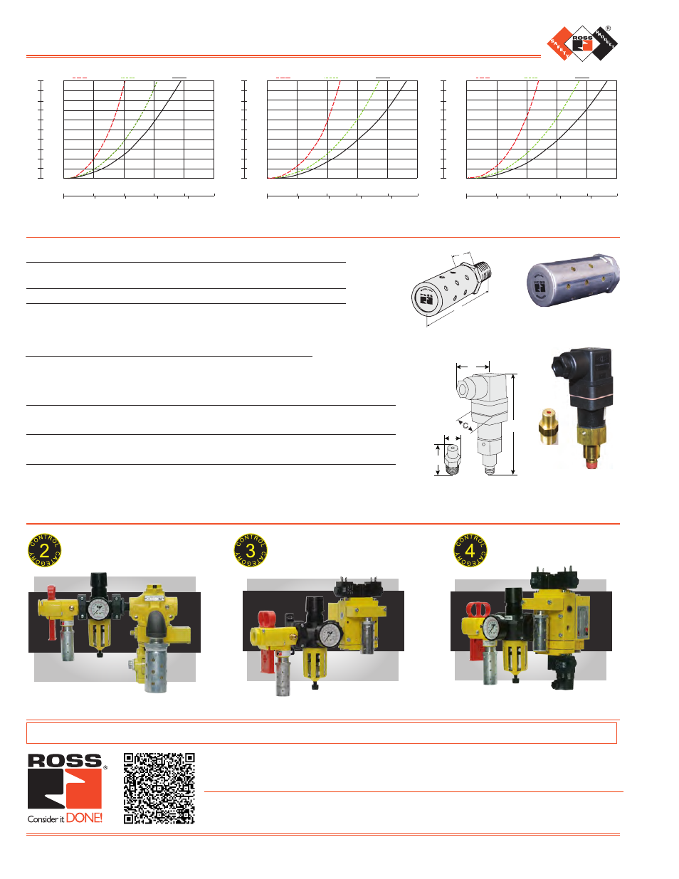
0
50
100
150
200
250
scfm
l/s 0
25
50
75
100
0
psid
DIFFERENTIAL PRESSURE
0.5
1
1.5
2
2.5
3
3.5
4
4.5
5
0
bar
0.03
0.06
Inlet pressure psig (bar)
36 (2.5)
92 (6.3)
145 (10.0)
0.10
0.14
0.17
0.21
0.24
0.28
0.31
0.34
1/4 Ports
0
50
100
150
200
250
scfm
l/s 0
25
50
75
100
0
psid
DIFFERENTIAL PRESSURE
0.5
1
1.5
2
2.5
3
3.5
4
4.5
5
0
bar
0.03
0.06
Inlet pressure psig (bar)
36 (2.5)
92 (6.3)
145 (10.0)
0.10
0.14
0.17
0.21
0.24
0.28
0.31
0.34
3/8 Ports
0
50
100
150
200
250
scfm
l/s 0
25
50
75
100
0
psid
DIFFERENTIAL PRESSURE
0.5
1
1.5
2
2.5
3
3.5
4
4.5
5
0
bar
0.03
0.06
Inlet pressure psig (bar)
36 (2.5)
92 (6.3)
145 (10.0)
0.10
0.14
0.17
0.21
0.24
0.28
0.31
0.34
1/2 Ports
LOCKOUT VALVE FLOW CHARACTERISTICS
MUFFL-AIR
®
Silencer
MUFFL-AIR
®
Silencer
M
odular
l-o-X
®
a
ir
E
ntry
P
ackagEs
E
XaMPlEs
Modular L-O-X
®
and
SV27 Sensing Valve
Modular L-O-X
®
and
DM
1
Series E
Pressure Switch
not shown
Modular L-O-X
®
and
DM
2®
Series E
For more information on Air Entry Packages, visit the Safety Industry page at www.rosscontrols.com.
•
May be installed on all L-O-X
®
valves and manual L-O-X
®
valves with EEZ-ON
®
operation with pressure sensing port
•
Provides a means to verify the release of downstream pressure to next obstruction
Visual Pop-Up Indicator or Pressure Switch (electrical)
Pop-Up
Indicator
Pressure Switch
Model Inlet Port Verification
Dimensions inches (mm)
Weight
Number
Size*
Option
A
B
C
lb (kg)
988A30
1/8
Pop-Up Indicator
0.55 (14) 0.98 (25)
–
0.03 (0.01)
586A86
1/8
Pressure Switch 2.01 (51) 4.3 (110) 1.22 (31) 0.28 (0.12)
* NPT port threads.
A
B
C
A
B
A
B
Port
NPT
Model
Avg. Dimensions inches (mm) Weight
Size Threads
Number
C
V
A B
lb (kg)
3/4
Male
5500A5013 7.0 1.3 (32)
3.8 (96)
0.5 (0.2)
* NPT port threads. For BSPP threads, add the letter “D” in front of the part number.
Pressure Range: 150 psig (10.3 bar) maximum.