Series w64 poppet valves, Pressure control, Iso 5599/i – Ross Controls 5599_I POPPET SERIES W64 User Manual
Page 2
13
www.rosscontrols.com
SERIES
W64
POPPET VALVES –
Pressure Control
1.0
2.1
4.0
1.0
2.1
4.0
1.0
2.1
4.0
1.0
2.1
4.0
1
2
3
1
2
3
1
2
3
1
2
3
W6456B2411
W6456B3411
W6456B4411
W6456B2417
W6456B3417
W6456B4417
W6456B2412
W6456B3412
W6456B4412
W6456B2418
W6456B3418
W6456B4418
33
33
50
16
16
16
33
33
50
16
16
16
2.9
1.2
0.7
2.9
1.2
0.7
2.9
1.2
0.7
2.9
1.2
0.7
5.9
2.3
1.2
5.6
2.3
1.1
5.9
2.3
1.2
5.6
2.3
1.1
0.8 (0.4)
1.3 (0.6)
2.3 (1.1)
0.8 (0.4)
1.3 (0.6)
2.3 (1.1)
0.8 (0.4)
1.3 (0.6)
2.3 (1.1)
0.8 (0.4)
1.3 (0.6)
2.3 (1.1)
4.4 (110)
5.1 (130)
6.4 (163)
4.4 (110)
5.1 (130)
6.4 (163)
4.4 (110)
5.1 (130)
6.4 (163)
4.4 (110)
5.1 (130)
6.4 (163)
1.7 (42)
2.1 (54)
2.6 (65)
1.7 (42)
2.1 (54)
2.6 (65)
1.7 (42)
2.1 (54)
2.6 (65)
1.7 (42)
2.1 (54)
2.6 (65)
1.8 (47)
2.1 (54)
2.3 (59)
1.8 (47)
2.1 (54)
2.3 (59)
1.8 (47)
2.1 (54)
2.3 (59)
1.8 (47)
2.1 (54)
2.3 (59)
Valve Model
Number
5/2 SINGLE REMOTE PILOT VALVES
5/2 DOUBLE REMOTE PILOT VALVES
Avg. Response Constants**
Dimensions
inches (mm)
F
M
Out-Exh.
In-Out
Weight
lb (kg)
Avg.
Cv
ISO
Size
Length
Width
Height
1 3
4
2
5
12
14
1 3
4
2
5
12
14
STANDARD SPECIFICATIONS
Ambient/Media Temperature Range:
40 to 175° F
(4 to 80° C).
High temperature models:
40 to 220° F (4 to 105° C).
Flow Media:
5 micron filtered air.
Inlet Pressure:
Vacuum to 150 psig (10 bar).
Pilot Pressure:
At least 30 psig (2 bar).
OPTIONS
Sub-Bases & Manifolds:
Page 14.
Regulators, Interposed:
Page 15.
Port
Sizes*
1/8 – 3/8
3/8 – 1/2
1/2 – 3/4
1/8 – 3/8
3/8 – 1/2
1/2 – 3/4
1/8 – 3/8
3/8 – 1/2
1/2 – 3/4
1/8 – 3/8
3/8 – 1/2
1/2 – 3/4
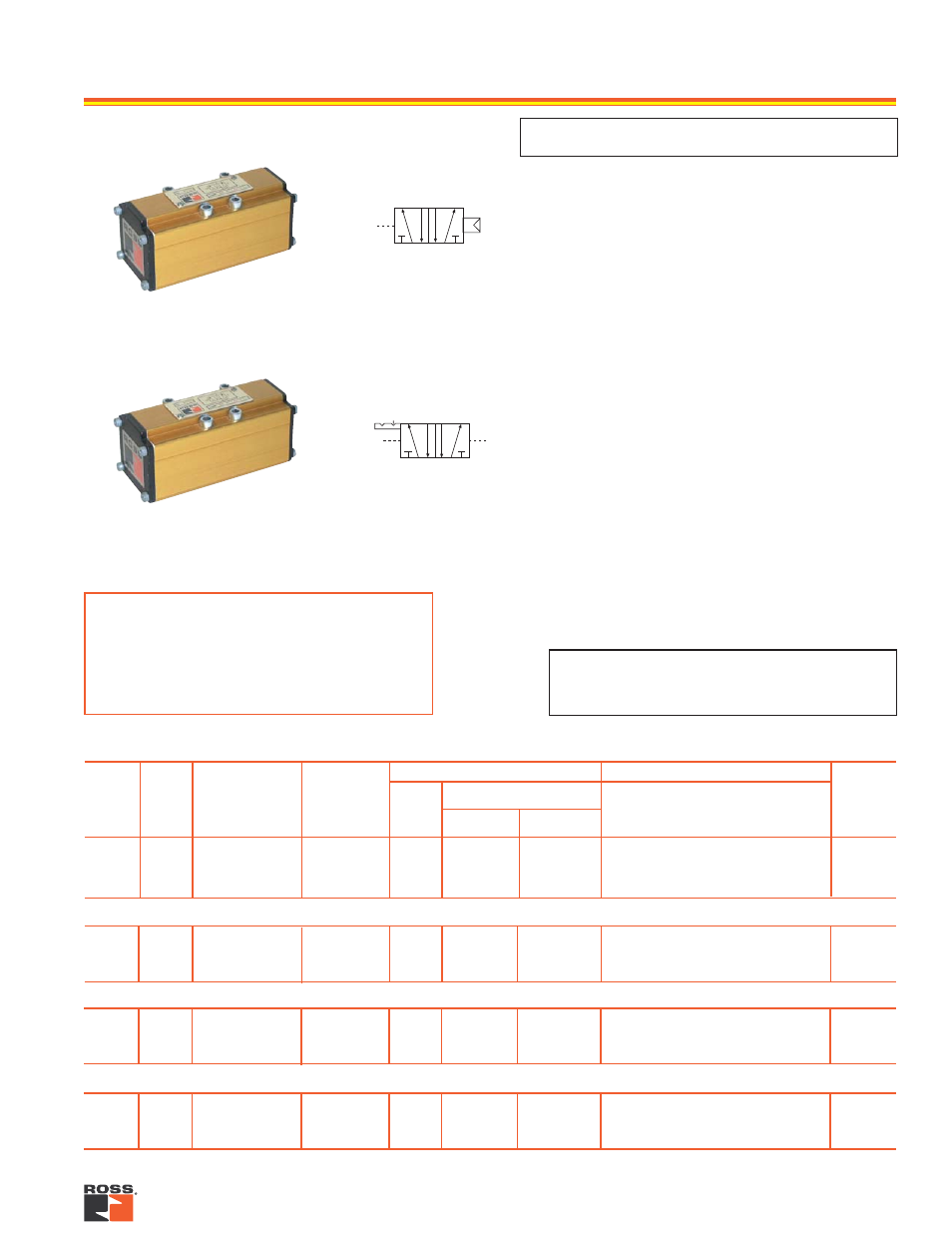
5/2 Single Remote Pilot Valve
5/2 Double Remote Pilot Valve
HIGH TEMPERATURE 5/2 SINGLE REMOTE PILOT VALVES
HIGH TEMPERATURE 5/2 DOUBLE REMOTE PILOT VALVES
IMPORTANT NOTE
Please read carefully and thoroughly the
CAUTIONS
on page 23.
**VALVE RESPONSE TIME (msec) = M + (F • V)
Average time required to fill volume V (cubic inches)
to 90% of supply pressure or to exhaust it to 10%
of supply pressure. M and F values are shown in
charts for each valve. See discussion of
Valve
Response Time
on page 22.
* Port sizes determined by customer’s choice of base or manifold. Bases and manifolds sold separately – see page 14.
ISO 5599/I