Airvantage servicing - control module, Exp view – Versa-Matic 2 Clamped Metallic Ball Valve Pumps (RE2) User Manual
Page 23
re2mdlAsmC-rev0314
www
.
versamatic
.
com
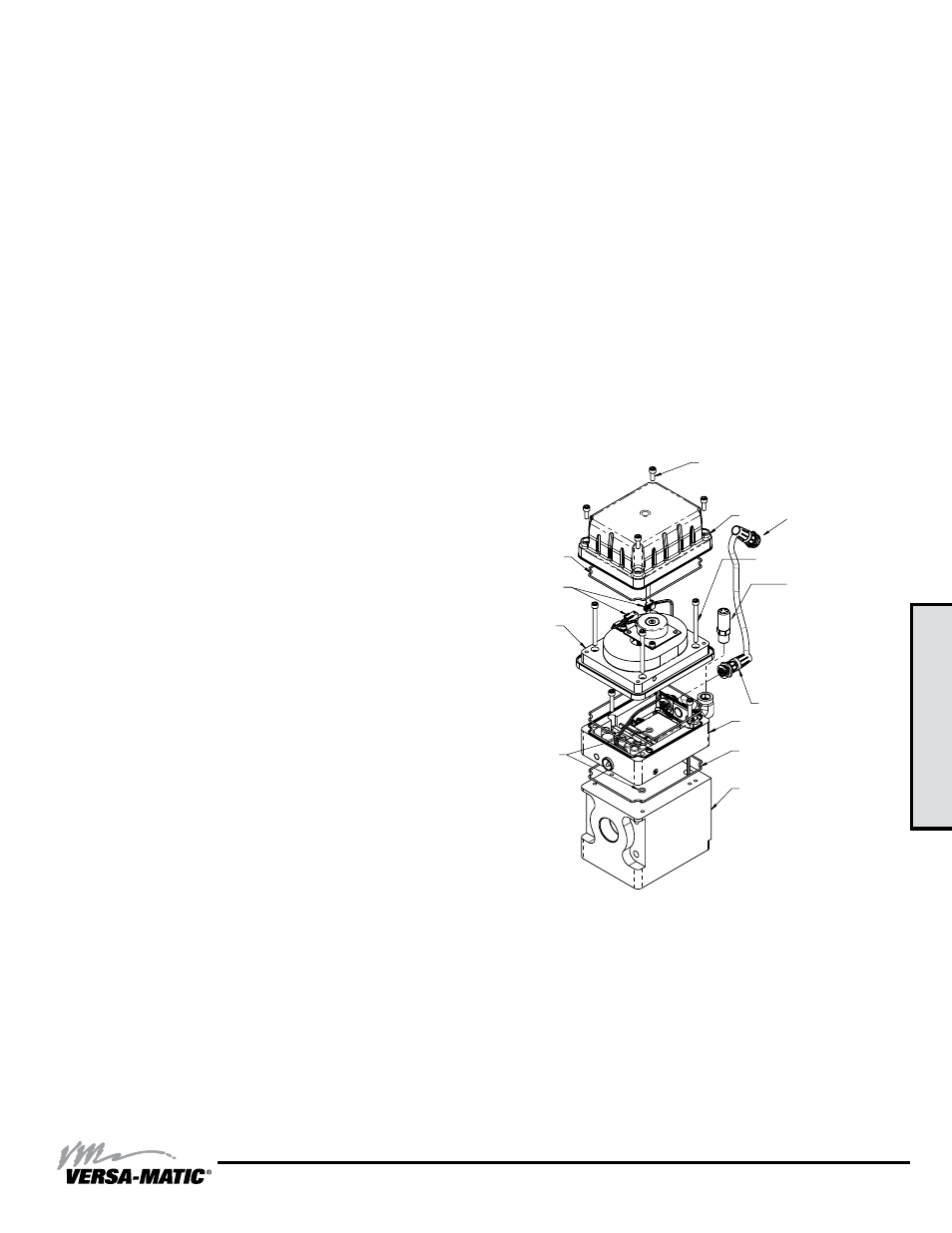
3: EXP
VIEW
Model RE2 Metallic Clamped •
20
airVantage Servicing - Control module
To service the control module, first shut off and bleed the air
being supplied to the pump. For safety purposes the air supply
line should be disconnected from the pump. Then shut off the
suction and discharge lines to the pump. Bleed the pressure
from the pump suction and discharge lines and remove the
lines from the pump. During the servicing of the AirVantage,
consult the “AirVantage Composite Repair Parts Drawing”.
Step #1: Remove the Patch Cable
Twist the ribbed portion of the patch cable connector in
a counterclockwise direction, until it unthreads from the
connector. The cable can either be removed from the
intermediate or from the control module.
Step #2: Remove the AirVantage from the Pump
Use a ½” socket and remove the four 5/16-18 x 5 1/2 cap
screws that hold the AirVantage to the pump. Remove the two
bolts that are holding the right side bracket to be able to remove
the right bracket and AirVantage unit from the pump. Be sure
to support the weight of the AirVantage while removing the last
cap screw. After the AirVantage is removed from the pump, set
the unit down on the plastic cover located on the bottom.
Step #3: Access the Pilot Valve
Use a 5/32 hex-key wrench and loosen the four 10-32 x .50
socket head cap screws securing the top cover on. Lift the
cover off, exposing the pilot valve. There is a molded o-ring
seal located on the underside of the cap. Make sure the o-ring
stays located within the groove. The connector will need to
be removed from the pilot valve. Once the plug has been
removed, feed the wire assembly into the hole in the valve
body to the point where the connector just enters the valve
body. Reinstall the top cover and loosely reinstall the bolts. The
connector will eventually need to be reconnected.
Step #4: Access the Control Module
Use a 5/32 hex-key wrench and loosen the four 10-32 x .50
socket head cap screws securing the bottom cover on. Lift
the bottom cover off, exposing the power generation module.
There is a molded o-ring seal located on the underside of the
cap. Make sure the o-ring stays located within the groove.
Unplug the connector that connects the power generator to the
control board. Use a 5/32 hex-key wrench to loosen the four
10-32 x 2 ¼ socket head cap screws. The power generation
module should now be loose. Carefully lift the power
generation module off the rest of the assembly, making sure
that the control board wire and connector slips through the hole
in the power generation case.
"AirVantage Caution" - Take caution not to lose the o-ring
that seals between the components.
If the control module needs to be replaced, use a 5/32 hex-
key wrench and loosen the two 10-32 x 1.00 socket head cap
screws holding the control module to the poppet assembly. The
control module should now be loose. Carefully lift the control
module off the poppet assembly, making sure that the pilot
valve connector wire slips through the hole in the poppet valve
assembly.
"AirVantage Caution" - Take caution not to loosen the
o-ring that seals between the components.
Step #5: Reinstalling
When reinstalling the new control module, make sure to feed
the pilot valve connector wire through the hole in the poppet
valve assembly. Install the two 10-32 x 1.00 socket head cap
screws and tighten to 30 in-lbs.
Reinstall the power generation module. Make sure to feed the
control module wire through the hole in the power generation
case. Install the four 10-32 x 2 ¼ socket head cap screws and
tighten to 60 in-lbs.
“AirVantage Caution” – Be sure to reattach the connector
from the power generator to the control board.
Reinstall the top cover, making sure the o-ring seal is still in the
groove. Tighten the four 10-32 screws. Reinstall the AirVantage
right bracket, chamber bolts/nuts and four 5/16-18 x 5 1/2 cap
screws, torque to 90 in-lbs.
“AirVantage Caution” – Be sure to reattach the patch cable
connector that connects the AirVantage module to the
intermediate.
CAPSCREW, HEX SOC HD
10-32 X .50
COVER
CAPSCREW, HEX SOC HD,
10-32 X 2.25
CONTROL MODULE
MUFFLER
VALVE, POPPET
SEAL, O-RING
POWER GENERATION
MODULE
O-RING
O-RING
SEAL, O-RING
CABLE, PATCH
CONNECTORS
(Control Module to
Power Generation Module)
CONNECTOR
(To Intermediate)
Note: Refer to AirVantage
Composite Repair Parts List
on page 18 for part numbers