Exp view – Versa-Matic 2 Clamped Metallic Ball Valve Pumps (RE2) User Manual
Page 21
re2mdlAsmC-rev0314
www
.
versamatic
.
com
3: EXP
VIEW
Model RE2 Metallic Clamped •
18
airVantage Servicing - Pilot Valve & Pressure Regulator
2.L
2.K
2.K
2.C
2.G
2.J
2.J
2.H
2.J
2.B
2.E
2.J
2.D
2.C
2.I
2.I
2.F
2.A
2.A
020.069.000
1
2.B
031.199.000
1
2.C
171.079.115
8
2.D
171.080.115
2
2.E
171.081.115
4
2.F
249.025.000
1
2.G
258.018.551
2
2.H
530.044.000
1
2.I
560.200.360
2
2.J
720.071.360
4
2.K
765.004.000
1
2.L
893.102.000
1
Optional 1/4" NPT Pipe Plug (P/N 618.011.330)
Must be installed if performing direct spray
wash-down of pump (Purchased Separately)
ITEM NO.
PART NUMBER
DESCRIPTION
QTY.
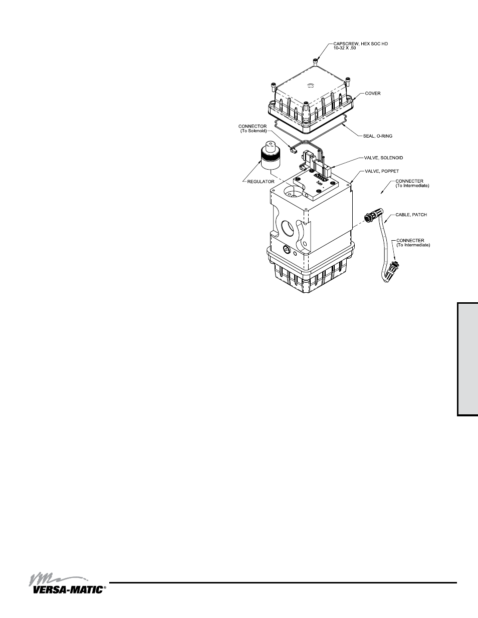
REGULATOR
POWER GENERATION MODULE
CAPSCREW, HEX SOC HD, 10-32 X .50
CAPSCREW, HEX SOC HD, 10-32 X 1.00
CAPSCREW, HEX SOC HD, 10-32 X 2.25
CONTROL MODULE
COVER
MUFFLER
O-RING
SEAL, O-RING
VALVE, SOLENOID
VALVE, POPPET
Pilot Valve and Pressure Regulator
To service the pilot valve or the pressure regulator, first shut
off and bleed the air being supplied to the pump. For safety
purposes the air supply line should be disconnected from
the pump. Then shut off the suction and discharge lines to
the pump. Bleed the pressure from the pump suction and
discharge lines and remove the lines from the pump. During
the servicing of the AirVantage, consult the “AirVantage
Composite Repair Parts Drawing”.
Step #1: Remove the Patch Cable
Twist the ribbed portion of the patch cable connector in
a counterclockwise direction, until it unthreads from the
connector. The cable can either be removed from the
intermediate or from the control module.
Step #2: Remove the AirVantage from the Pump
Use a ½” socket and remove the four 5/16-18 x 5 1/2 cap
screws that hold the AirVantage to the pump. Remove the two
bolts that are holding the right side bracket to be able to remove
the right bracket and AirVantage unit from the pump. Be sure
to support the weight of the AirVantage while removing the last
cap screw. After the AirVantage is removed from the pump, set
the unit down on the plastic cover located on the bottom.
Step #3: Access the Pilot Valve and Pressure Regulator
Use a 5/32 hex-key wrench and remove the four 10-32 x .50
socket head cap screws securing the top cover on. Lift the
cover off, exposing the pilot valve and pressure regulator.
There is a molded o-ring seal located on the underside of the
cap. Make sure the o-ring stays located within the groove.
If the pilot valve needs to be replaced, unplug the connector
attached to it. Use a jeweler's screwdriver and remove the
two screws holding the pilot valve to the plate. The valve and
gasket can now be removed and/replaced. When reinstalling
the pilot valve, tighten the screws to snug with a jeweler's
screwdriver.
“AirVantage Caution” – Be sure to reattach the connector
to the pilot valve.
If the pressure regulator needs to be replaced, use slip-joint
pliers to unscrew the regulator from the body by turning it in a
counterclockwise direction.
“AirVantage CAUTION” – Do not loosen or tighten the
regulator by turning the knurled portion of the unit. Place
the slip-joint pliers on the smooth area underneath the
knurled area of the regulator.
Step #4: Reinstallation
Reinstall the top cover, making sure the o-ring seal is still in the
groove. Tighten the four 10-32 screws.
Reinstall the AirVantage right bracket, chamber bolts/nuts and
four 5/16-18 x 5 1/2 cap screws, torque to 90 in-lbs.
“AirVantage Caution” – Be sure to reattach the patch cable
connector that connects the AirVantage module to the
intermediate.
Note: Refer to Composite Repair Parts
List on page 18 for part numbers