Airvantage sensor servicing – Versa-Matic 2 Clamped Metallic Ball Valve Pumps (RE2) User Manual
Page 19
re2mdlAsmC-rev0314
www
.
versamatic
.
com
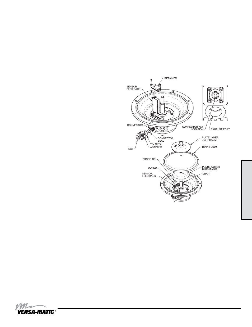
3: EXP
VIEW
Model RE2 Metallic Clamped •
16
airVantage Sensor Servicing
INTERMEDIATE AND AirVantage SENSOR SERVICING
To service the intermediate and AirVantage sensor, first shut
off and bleed the air being supplied to the pump. For safety
purposes, the air supply line should be disconnected from
the pump. Shut off both the suction and discharge lines to the
pump. Consult the “Composite Repair Parts Drawing”.
Step #1: Remove the Patch Cable
Twist the ribbed portion of the patch cable connector in
a counterclockwise direction, until it unthreads from the
connector. The cable can either be removed from the
intermediate or from the control module.
Step #2: Remove the AirVantage from the Pump
Use a ½” socket and remove the four 5/16-18 x 5 1/2 cap
screws that hold the AirVantage to the pump. Remove the two
bolts that are holding the right side bracket to be able to remove
the right bracket and AirVantage unit from the pump. Be sure
to support the weight of the AirVantage while removing the last
cap screw. After the AirVantage is removed from the pump, set
the unit down on the plastic cover located on the bottom.
Step #3: Remove the Manifolds, Chambers, and
Diaphragms (Refer to exploded views for disassembly)
Step #4: Remove the Diaphragm Assemblies
Refer to exploded views for disassembly.
“AirVantage CAUTION” – When the diaphragm assembly
is removed, watch for the brass probe tips located on the
end of the sensor rod. There is one brass probe tip and
one o-ring per side. Inspect the probe tips and o-rings for
wear. For every diaphragm service, these parts should
be replaced and are available in kit form. Consult the
“Composite Repair Parts Drawing” for part numbers and
quantities.
Step #5: Accessing the AirVantage Sensor
Use a 9/64" hex key wrench to remove the 4 socket head cap
screws from the sensor connector plate. Use a 13/16" socket
and remove the plastic nut securing the connector to the
connector plate. Remove the connector from the connector
plate taking care not to lose/misplace the gasket on the
connector or the o-ring that seals the connector plate. Next,
use a 9/64" hex key wrench to remove the 2 socket head cap
screws on each sensor end cap. Use a small flat screwdriver
to gently pry the end caps from the inner chambers. Now slide
the sensor out of the intermediate while feeding the connector
and cable into the intermediate. Slide the Connector end of
the cable out of the same opening as the sensor.
Step #6: Reinstallation
Note that the orientation of the sensor rod with respect to the
pilot shaft location. The sensor rod side of the sensor should
be on the "top" side of the pump (facing the air valve side of
the pump). Slide the Connector end of the cable and then
the sensor into the sensor opening. Feed the connector out
through the opening in the intermediate. Ensure the gasket
is on the connector and the connector plate o-ring is in the
connector plate o-ring groove. Insert the connector into the
connector plate. Use a 13/16" socket to install the plastic nut
in order to secure the connector to the connector plate. Use a
9/64" hex key wrench to install the 4 socket head cap screws
and secure the sensor connector plate to the intermediate.
Install the sensor end caps. Be sure not to pinch or cut the
sensor o-rings. Use a small amount of lubrication if necessary
to ease assembly. Use a 9/64" hex key wrench to install the 2
socket head cap screws on each sensor end cap to secure the
sensor.