Hose reel operations manual – Reelcraft Nordic Series 2000 Reels User Manual
Page 3
Hose Reel Operations Manual
www.reelcraft.com
Page 3
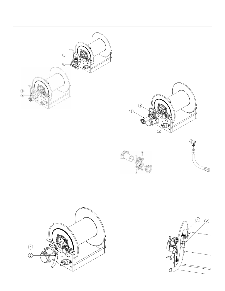
AIR DRIVEN REELS
1. Apply thread compound to
inlet air line fitting (1) and
pneumatic motor (2) inlet
threads.
2. Connect inlet air line
(1) to motor (2).
HYDRAULIC DRIVEN REELS
1. Apply thread compound inlet / outlet hydraulic line fittings
(1) and hydraulic motor inlet threads (2).
2. Thread hydraulic line fittings (1) into motor inlet / outlet (2)
tighten securely.
INLET CONNECTION
NOTE: Install a union fitting as near as possible to the swivel
joint inlet, so the joint can be easily removed for servicing.
CONNECTING THE SUPPLY LINE FOR THREADED INLET
SWIVELS
NOTE: Avoid strain on swing joint at all times. Threaded type
swivel inlets must be connected to the fluid supply by using a
flexible connector.
1. Apply thread compound to the swivel (1) and connecting
hose fitting (2) threads.
2. Thread connecting hose fitting (2) into swivel (1). Tighten
securely.
3. With control valve open, fully extend and charge hose
to purge system of gases. When fluid appears at control
valve, close valve. This prevents flattening of hose and ex-
cessive pressure on drum when fluid supply is reinitialized
at a later time.
VICTAULIC INLET SWIVELS
NOTE: Victaulic - Type swivel joint inlet connections must be
carefully aligned. Two victaulic connections, correctly installed,
allow adequate flexibility for smooth rotation.
1. Connect victaulic coupling onto inlet swivel fitting and inlet
supply line
2. Adjust inlet supply line to verify flexibility exists for proper
alignment.
3. With control valve open, fully extend and charge hose
to purge system of gases. When fluid appears at control
valve, close valve. This prevents flattening of hose and ex-
cessive presure on drum when fluid supply is reinitialized
at a later time.
VICTAULIC
CONNECTION
FLEXIBLE
CONNECTION
NOTE: Failure to
use flexible con-
nector with any
live reel will void
warranty
For larger reels, gooseneck may be removed from reel to fit to
hose. Note that if the reel has a welded or threaded riser in the
fluid path assembly, it cannot be removed to attach the hose.
CAUTION: Do not connect the output hose to the gooseneck
(1) until after the reel is installed and motor connections are
complete. Fill the hose before winding on the reel to prevent
excessive pressure on the drum when hose is filled.
1. Apply thread compound
to connecting gooseneck
(1) and output hose fitting
threads (2).
2. Hand thread output hose
fi tting (2) into gooseneck
(1).
3. Using a wrench, fi rmly
hold gooseneck (1) while
tightening out put hose fit-
ting (2).