Introduction, Ramm full wave solid state dc motor speed control – Rapid-Air DUAL SWIVEL REEL WITH DISPLAY KEYPAD: 100 & 1000 SERIES User Manual
Page 9
The RAMM Full Wave Solid State DC
Motor Speed Control represents the
latest state-of-the-art design achiev-
able through modern technology.
FeatUreS inCLUDe:
integrated Circuitry
Used to control and amplify
command and reference levels
with both closed and open loop
feedback to provide superior
motor regulation. (Speed changes
due to load, line voltage, or
temperature variations are held to
minimum levels).
High Quality Components
Selected and tested for proven
dependability.
transient protection
Used to prevent failure of the
power bridge circuit caused by
voltage spikes on the AC line.
High reliability
When used in accordance with
instructions in this manual, the
RAMM will provide years of
trouble free operation.
a. initiaL SetUp anD Wiring
general instructions
1. Install proper size Plug-In
Horsepower Resistor. (see table 2)
2. The RAMM can be connected
to a standard 120V or 240V
50/60 Hz AC line (be sure the
AC input voltage corresponds
to the control voltage rating and
the motor rating). (e.g. 90-130 VDC
motor on 120VAC and 180 VDC
motor on 240 VAC)
3. Follow the recommended supply
wire sizes as per table 3.
4. Follow the NEC and other
electrical codes that apply.
CaUtion: SEPARATE BRANCH
PROTECTION MUST BE PROVIDED
ON 240V CIRCUITS.
5. Connect control in accordance
to connection diagram.
introduction
raMM Full Wave Solid State DC Motor Speed Control
taBLe 3: MiniMUM SUppLY Wire SiZe reQUireMentS
1
2
3
Max.
Motor
Amps
(DC Amps)
6.0
12.0
16.0
1/2
1
1-1/2
14
12*
12
16
14
12
* Maximum recommended wire size.
Max.
Motor
HP
90V
Max.
Motor
HP
180V
Max.
Motor
Run
Minimum
Wire Size (AWG)
Cu only)
Max. Motor Run
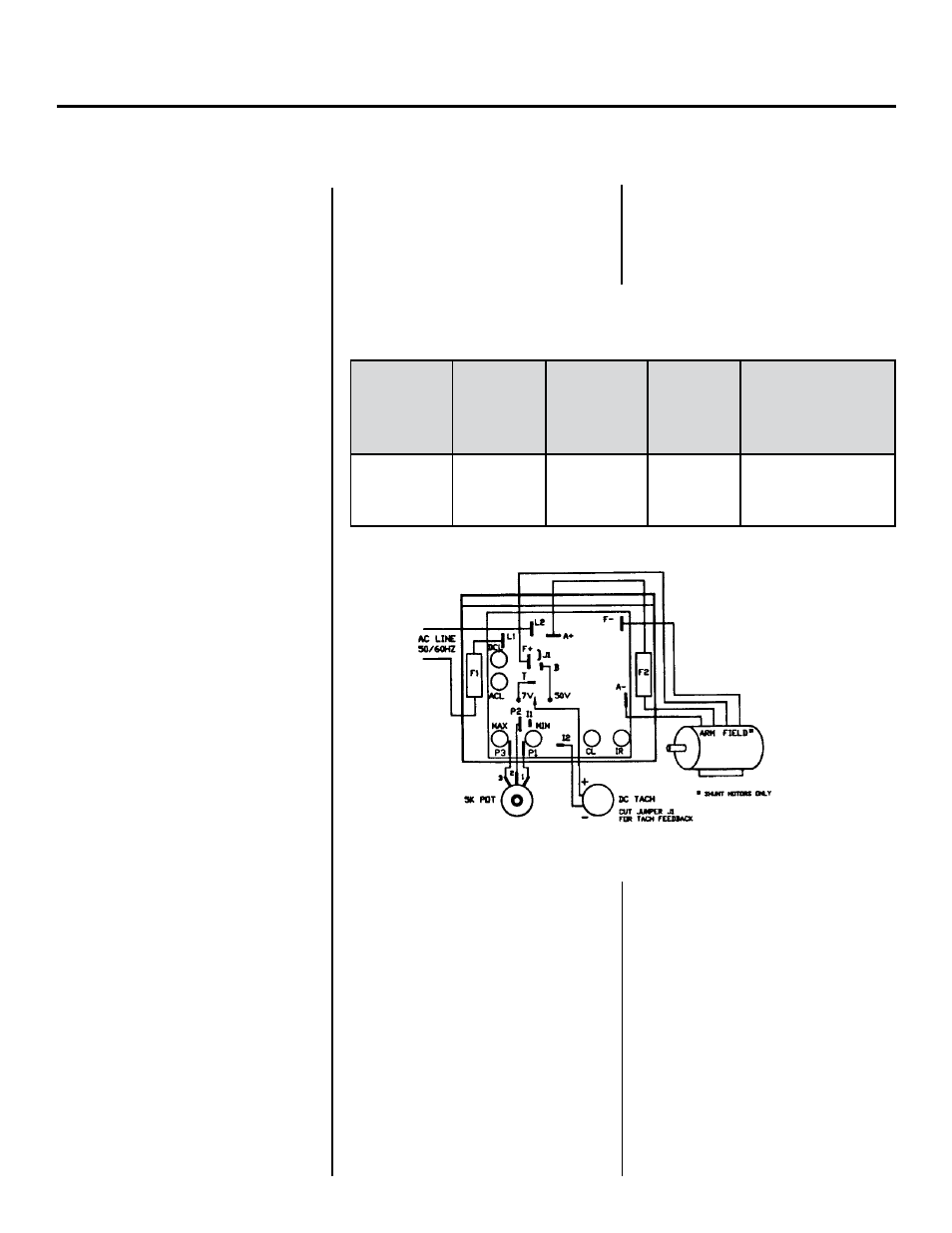
FigUre 1: BaSiC raMM ConneCtion DiagraM
CaUtion: DO NOT BUNDLE
POTENTIOMETER CONNECTIONS
(P1, P2, P3) AND INHIBIT
CONNECTIONS (I1, I2) WITH
AC LINE OR MOTOR WIRES.
B. VoLtage FoLLoWing
All models can be controlled with an
isolated analog reference voltage
(0-6VDC) in lieu of the main speed
potentiometer. The voltage is con-
nected to P2 (+) and F-. The control
output voltage will linearly follow the
input voltage. The source impedance
of the input should be 10K ohms or
less. The Min trimpot can be used to
provide an offset speed. If an offset is
not required, adjust the Min to 0+ or
0– speed as desired. The Max trimpot
is rendered inoperative in the voltage
following mode. Use auxiliary trimpot
to limit the control range. If the input
signal is not isolated, or is a current
signal (4-20 MA), the RASI240D Signal
Isolator must be used. It will allow
direct connection to process control-
lers and microprocessors.