Ramsey Winch ATV REPLACEMENT MINI ROCKER SWITCH FOR WIRELESS 256129 User Manual
Page 3
3
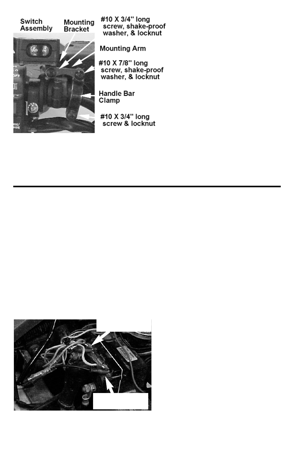
6. Tighten all screws for the handle
bar clamps and mounting brackets
securely, positioning the rocker
switch as desired.
7. Route the Rocker Switch wire
down the handle bars to where the
solenoid is installed. Turn the han-
dle bars fully right and left to
ensure enough slack in the wire.
Make sure wire is not drawn taut
across any surface that could
damage it. Use cable ties to
anchor wire. Do not connect wires
to solenoid yet.
8. Push ATV Accessory wire and red
wire from switch into plastic splice
(item #1-10). Fold splice clip over
itself and snap closed.
Finish Installation
1. Unplug spade connectors from solenoid.
Connect black wire from switch into right
terminal (terminal above black with yel-
low stripe motor lead). Connect green
wire from switch into left terminal (termi-
nal above black motor lead).
2. Plug the spade connectors for the exist-
ing wireless remote into the “piggyback”
plugs above the switch wires. Plug the
yellow wire above the black switch wire
and the green wire above the green
switch wire. See below.
3. Confirm that winch clutch is disengaged.
4. Connect negative (-) battery cable to
vehicle battery. Connect Black Battery
Lead from winch to negative (-) vehicle
battery terminal.
5. With ignition switch OFF, press Rocker
switch to “OUT”—winch should not
operate. If the winch does operate with
the ignition off, confirm that proper
accessory wire from ignition was spliced.
6. Spool a few feet of cable out by hand.
Engage winch clutch. Turn ignition switch
ON and press Rocker switch to “OUT”—
winch should spool cable out. If winch
does not operate with ignition on, check
wiring against the schematic on page 1.
7. If winch spools cable IN instead of OUT,
turn off ignition and reverse black and
green wires on solenoid.
Black switch wire
and yellow wire
Green switch wire
and green wire