Components and specifications – Qualcraft SkyMast Skyhook User Manual
Page 9
G
ua
rd
ia
n
Fa
ll
Pr
ot
ec
ti
on
6
30
5
S.
2
31
st
S
t.
, K
en
t,
W
A
9
80
32
p
ho
ne
: (
80
0)
4
66
-6
38
5
f
ax
: (
80
0)
6
70
-7
89
2
w
w
w
.g
ua
rd
ia
nf
al
l.c
om
7
Components and Specifications
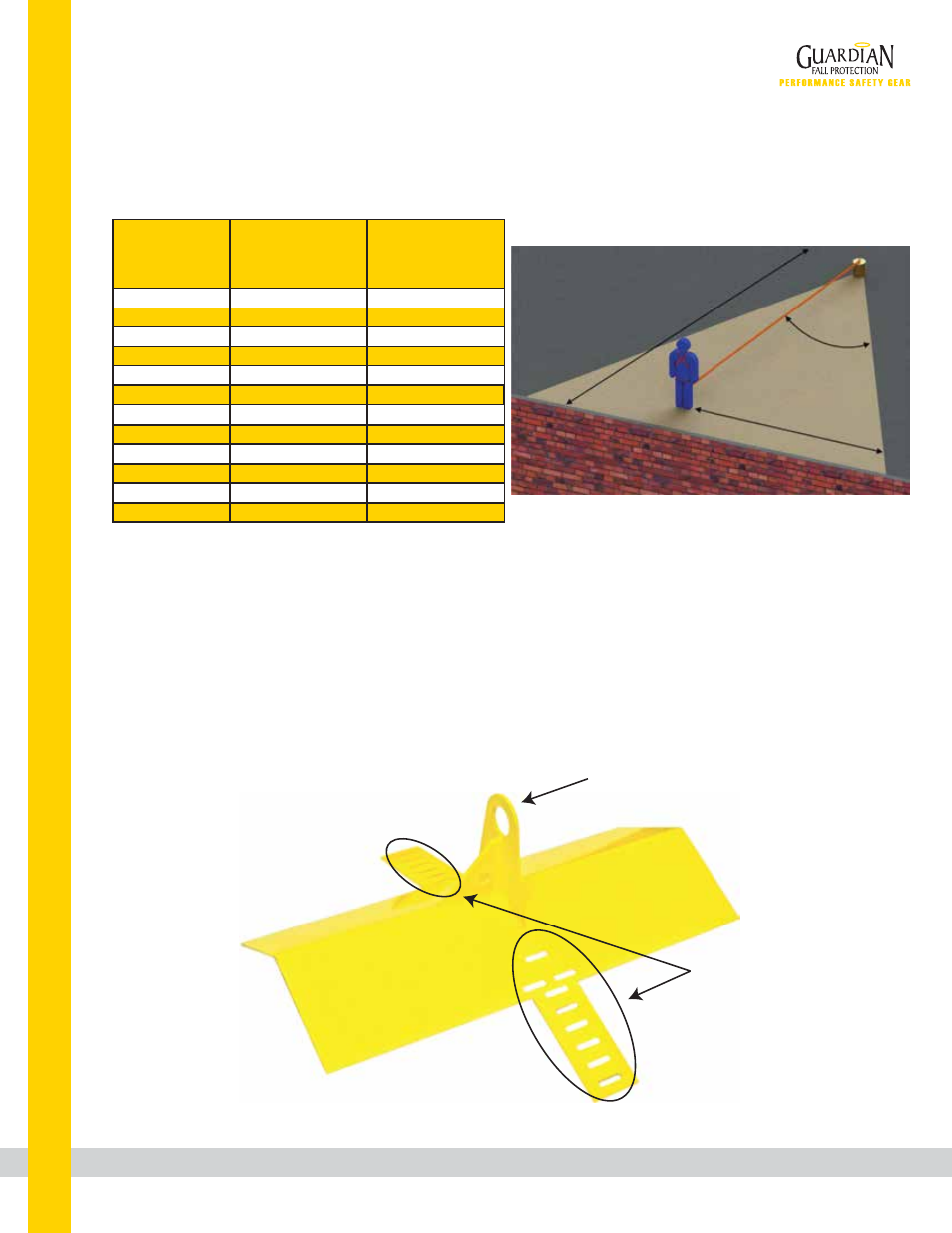
Correct Anchorage Positioning:
This chart details allowable working zones required
to reduce risk of swing falls and improper side loading.
ALWAYS adhere to information specified by chart.
Anchor Distance
From
Leading Edge (Y)
Working Distance
Along Roof Edge
(Either Direction) (X)
Working Angle
From
Perpendicular (Ø)
6’
10’
15’
20’
25’
30’
35’
40’
45’
50’
55’
60’
8’
9’ - 9”
11’ - 7”
13’ - 3”
14’ - 6”
16’
17’ - 2”
18’ - 3”
19’ - 4”
19’ - 10”
21’ - 4”
22’ - 3”
53°
45°
38°
33°
30°
28°
26°
24°
23°
21°
21°
21°
For example, if the anchorage connector is 6’ from the leading
edge (Y), the working distance (X) is 8’ in each direction from
the perpendicular, which translates to a 53° working angle.
Key:
X: Working Distance
Along Roof Edge
Y: Distance From
Leading Edge
Ø: Total Working
Angle
Y
X
Ø
Materials: powder-coated steel.
Connection Point
Fastener Installation
Locations