Operation, Warning opera t or’s manual, B-10 – Lincoln Electric IMt10143 MARQUETTE AutoPro 140_180 User Manual
Page 19
B-10
OPERATION
B-10
AUTOPRO™ (140/180 MODELS)
(See Figure B.16)
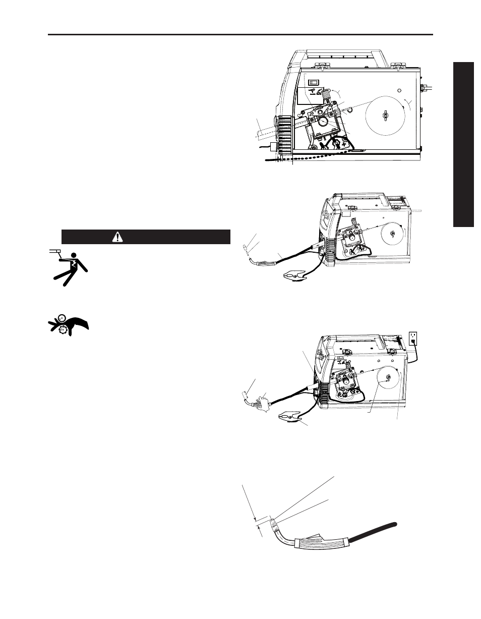
6. Feed the wire through the incoming guide, over
the drive roll groove, thru the outgoing guide and
wire drive outlet on the gun side.
7. Close the Pivot Arm Assembly and secure by
rotating the Tension Arm Assembly back to the up
position. (See Tension information on decal.)
(See Figure B.17)
8. Remove the nozzle from the gun and contact tip
and straighten the gun out flat.
9. Turn the machine power switch to on and press
the gun trigger to feed wire through the gun liner
until the wire comes out of the threaded end of the
gun several inches. (See Figure B.18)
10. When trigger is released, the spool of wire should
not unwind. Adjust wire spool brake accordingly.
MOVING PARTS AND ELECTRICAL
CONTACT CAN CAUSE INJURY OR BE
FATAL.
•When the gun trigger is depressed
drive rolls, spool of wire and electrode
are ELECTRICALLY LIVE (HOT).
• Keep away from moving parts and
pinch points.
• Keep all doors, covers, panels and
guards securely in place.
DO NOT REMOVE OR CONCEAL
WARNING LABELS.
-----------------------------------------------------------------------
11. Install the .025”(0.6mm) contact tip.
12. Install the nickel MIG welding nozzle to the gun.
13. Trim the wire stickout to 3/8”(9.5mm) from the
nozzle end. (See Figure B.19)
14. Close the wire drive compartment door. The
machine is now ready to weld.
15. "Learn to Weld" Video is on the DVD.
16. Based on the thickness of the material you are
going to weld and the type and diameter of the
welding wire, set the voltage and the wire feed
speed per the procedure decal attached to the
inside of the wire drive compartment door. The
settings listed on the procedure decal are sugges-
tions. The dials may need to be adjusted to
accommodate the application, input voltage or
user preference.
TENSION ARM ASSEMBLY
LOCKED IN UP POSITION
PIVOT ARM ASSEMBLY
WITH BEARING PRESSING AGAINST DRIVE ROLL
DIRECTION
OF WIRE
WIRE SPOOL
.025" (0.6mm)
L-56 Solid
MIG WIRE
DRIVE ROLL
INCOMING
GUIDE
OUTGOING GUIDE
BEARING
SLIDE WIRE
INTO GUN
CONNECTOR
SIDE
WIRE SPOOL
.025" (0.6mm)
L
-56 S
OLID M
IG
REMOVED NOZZLE
REMOVED CONTACT TIP
LAY CABLE AND GUN STRAIGHTEN
IN THIS POSITION
PLUG IN POWER
INPUT CORD
DEPRESS TRIGGER
TO ACTIVATE WIRE,
WHICH FEEDS THE WIRE
THRU THE LINER.
FEED WIRE
APPROXIMATELY 4.00"
FROM THE GUN TUBE END
ON/OFF
SWITCH
WORK CLAMP AND CABLE
ROTATION
WIRE SPOOL
WIRE SPOOL BRAKE
.025" (0.6mm)
L-5
6 SOLID M
IG
INSTALL .025(0.6mm) CONTACT TIP
INSTALL NICKEL NOZZLE
TRIM WIRE
STICKOUT
3/8"(9.5mm)
from the Nickel Nozzle
FIGURE B.17
FIGURE B.18
FIGURE B.19
FIGURE B.16
WARNING
OPERA
T
OR’S MANUAL