Operation, Controls and settings, Opera t or’s manual – Lincoln Electric IMt10143 MARQUETTE AutoPro 140_180 User Manual
Page 11
B-2
OPERATION
B-2
AUTOPRO™ (140/180 MODELS)
CONTROLS AND SETTINGS
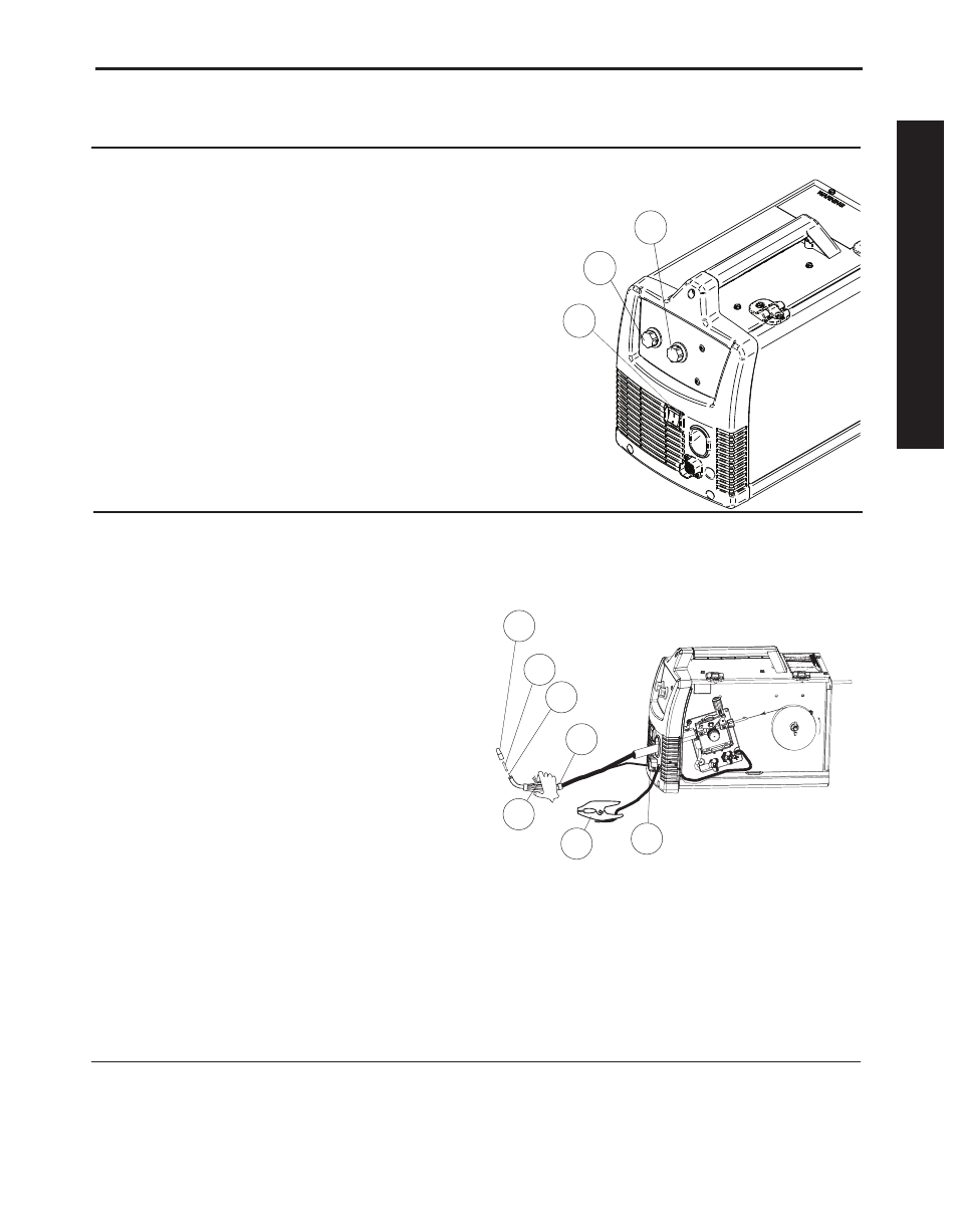
This machine has the following controls:
See Figure B.1
1. POWER SWITCH – Turns power on and off to the
machine.
2. ARC VOLTAGE CONTROL – This knob sets the
output voltage of the machine. Along with wire feed
speed (WFS), this control sets a weld procedure.
Refer to the procedure decal on the wire drive com-
partment door to set a welding procedure based on
the type of material and thickness being welded.
3. WIRE FEED SPEED CONTROL (WFS) – This
knob sets the speed that the machine feeds wire.
Along with arc voltage, this control sets a weld pro-
cedure. Refer to the procedure decal on the wire
drive compartment door to set a welding procedure
based on the type of material and thickness being
welded.
See Figure B.2
4. GUN TRIGGER – Pressing the trigger activates the
wire drive and energizes the output of the machine.
Press the trigger to weld and release the trigger to
stop welding.
5. WELDING GUN – Delivers wire and welding cur-
rent to the work piece.
a. Gun Liner – wire travels through the liner from
the wire drive. The gun liner will feed .025” to
.035”(0.6mm to 0.9mm) wire.
b. Contact Tip – provides electrical contact to the
wire.
c. Nozzle – When flux-cored welding, the black noz-
zle protects the mounting threads on the gun.
When MIG welding, the nickel nozzle funnels the
shielding gas to the weld.
6. WORK CLAMP & CABLE – Clamps to the work
piece being welded and completes the electrical
welding circuit.
7. GUN TRIGGER CONNECTOR RECEPTACLE –
Plug the 4 pin gun trigger connector into this recep-
tacle.
11
33
22
FIGURE B.1
FIGURE B.2
4
5a
5b
5
5c
6
7
.035"(0.9mm)
NR-211-MP
WIRE SPOOL
OPERA
T
OR’S MANUAL