Operation, C. connect leads and cables on the machine, D. load wire spool – Lincoln Electric IMt10143 MARQUETTE AutoPro 140_180 User Manual
Page 18: Figure b.15 figure b.14
B-9
OPERATION
B-9
AUTOPRO™ (140/180 MODELS)
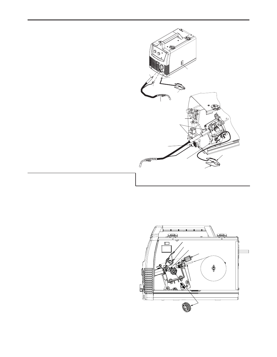
C. CONNECT LEADS AND CABLES ON
THE MACHINE
(See Figure B.14)
1. Open the case side door.
2. Slide the connector end of the gun and cable
through the hole of the machine front and into the
gun connector bushing on the wire drive. Tighten
thumbscrew to connector bushing.
3. Make sure the gun connector end is seated fully
into the wire drive.
4. Plug the gun trigger lead connector into the 4 pin
gun trigger receptacle on the machine front.
5. Wire Drive Polarity. MIG welding requires Positive
(+) polarity. Connect the short power cable from
the wire drive to the positive (+) output terminal and
tighten wingnut.
6. Work Lead Connection. Slide the lugged end of the
work cable through the hole in the machine front
and route cable through the strain relief as shown in
figure B.14. Place lug on the negative (-) output ter-
minal and tighten wing nut.
D. LOAD WIRE SPOOL
(See Figure B.15)
1. Locate the sample spool of .025”(0.6mm) L-56 solid
MIG wire and place onto wire spool spindle. Orient
the spool so that the wire feeds off the top of the
spool.
2. Secure spool in place by tightening the wing nut
against the spacer that holds the wire spool on the
spindle.
3. Open the pivot arm assembly by rotating the ten-
sion arm assembly down and lift pivot arm assem-
bly up.
4. Remove drive roll by un-screwing the black knob that
holds the drive roll on. Install the Dual Track drive roll
with the .025”(0.6mm) mark facing outward which will
allow feeding of .025”(0.6mm) L-56 Solid MIG wire.
5. Carefully unwind and straighten the first six inches
of welding wire from the spool. Hold onto the wire
until the the Pivot Arm assembly and Tension Arm
are locked in place. This will prevent the wire from
unspooling.
GUN AND CABLE
WORK CLAMP
(4 PIN)
LEAD CONNECTOR
TERMINAL END
(FITS ON STUD INSIDE
SEE FIGURE BELOW)
SLIDE
CONNECTOR
END HERE
OPEN LATCH DOOR
LOCATE COMPONENTS
TO CONNECT TO THE
FRONT OF MACHINE
WORK CLAMP
(4 PIN)
TRIGGER RECEPTACLE
PLUGGED IN
ALL COMPONENTS SHOWN CONNECTED
(FRONT AND SIDE DOOR IS REMOVED
FOR CLARITY)
SHORT POWER
CABLE POSITIVE "+"
OUTPUT TERMINAL
WORK LEAD
CONNECTION
NEGATIVE "-"
OUTPUT TERMINAL
GAS LINE
TIGHTEN THUMB SCREW TO
CONNECTOR BUSHING
FIGURE B.15
FIGURE B.14
WIRE SPOOL
.025" (0.6mm)
L-56 SOLID
MIG WIRE
DRIVE ROLL
PIVOT ARM ASSEMBLY
TENSION ARM ASSEMBLY
OUTGOING GUIDE
BEARING
INCOMING GUIDE