Installation, Caution, Caution warning – Lincoln Electric IM10058 POWER WAVE STT MODULE User Manual
Page 10: Connection between power source and stt, Module (arclink, And differential i/o pigtails), Electrode and work connections
A-3
INSTALLATION
POWER WAVE
®
STT
®
MODULE
A-3
Regarding cable placement, best results will be
obtained when control cables are routed separate from
the weld cables. This minimizes the possibility of inter-
ference between the high currents flowing through the
weld cables, and the low level signals in the control
cables. These recommendations apply to all communi-
cation cables including ArcLink
®
connections.
------------------------------------------------------------------------
CONNECTION BETWEEN POWER SOURCE
AND STT
®
MODULE (ARCLINK
®
AND
DIFFERENTIAL I/O PIGTAILS)
The pigtail connections on the STT
®
Module include all sig-
nal and power lines required for proper operation. With the
STT
®
Module securely fastened to the power source, con-
nect the pigtails to their respective receptacles on the back
of the power source per the connection diagrams located in
the “Installation Section”.
Special Instructions:
K2902-1
Some earlier vintage S350 power sources (Code 11589)
may not include a 6-pin Differential I/O receptacle. If the
receptacle is not present on the host power source, contact
the Lincoln Electric Service Department to obtain an
S350/STT Retrofit Kit (S28481).
STT
®
Module to ArcLink
®
Wire Feeders (K1543 or K2683
ArcLink
®
Control Cable)
The K2902-1 STT
®
Module includes an ArcLink
®
output
receptacle for connection to compatible wire feeders. The
control cable consists of two power leads, one twisted pair
for digital communication, and one lead for voltage sensing.
The 5 pin ArcLink
®
receptacle is located on the lower rear
portion of the STT
®
Module. The control cable is keyed and
polarized to prevent improper connection. Best results will
be obtained when control cables are routed separate from
the weld cables, especially in long distance applications.
The recommended combined length of the ArcLink
®
control
cable network should not exceed 200ft.
ELECTRODE AND WORK CONNECTIONS
Connect the electrode and work cables per the connection
diagrams included in this document. Size and route the
cables per the following:
• Positive Electrode Polarity: Most welding appli-
cations run with the electrode being positive (+).
For those applications, connect the electrode cable
between the wire drive feed plate and the output
stud on the STT
®
Module. Connect a work lead
from the negative (-) power source output stud to
the work piece per the Connection Diagram.
(See Figure A.5)
• Negative Electrode Polarity: The STT
®
process CANNOT
be run using negative electrode polarity. However, for
processes other than STT
®
requiring negative polarity, such
as some Innershield applications, the electrode and work
connections should be reversed at the load, NOT at the
input to the STT
®
Module. Connect the electrode cable to
the negative (-) stud of the power source, and work cable to
the output stud of the STT
®
Module per the Negative Polarity
Connection Diagram. (See Figure A.2)
Never reverse the polarity to the input of the STT
®
Module (DO NOT connect the negative stud of the
power source to input stud of the STT
®
Module).
This may result in damage to the STT
®
Module!
------------------------------------------------------------------------
-
Negative electrode polarity operation may require
reconfiguration of the power source voltage sense
leads. See the Remote Sense Lead section in the
power source instruction manual for further
details.
------------------------------------------------------------------------
For additional Safety information regarding the elec-
trode and work cable set-up, See the standard
“SAFETY INFORMATION” located in the front of the
Instruction Manuals.
CAUTION
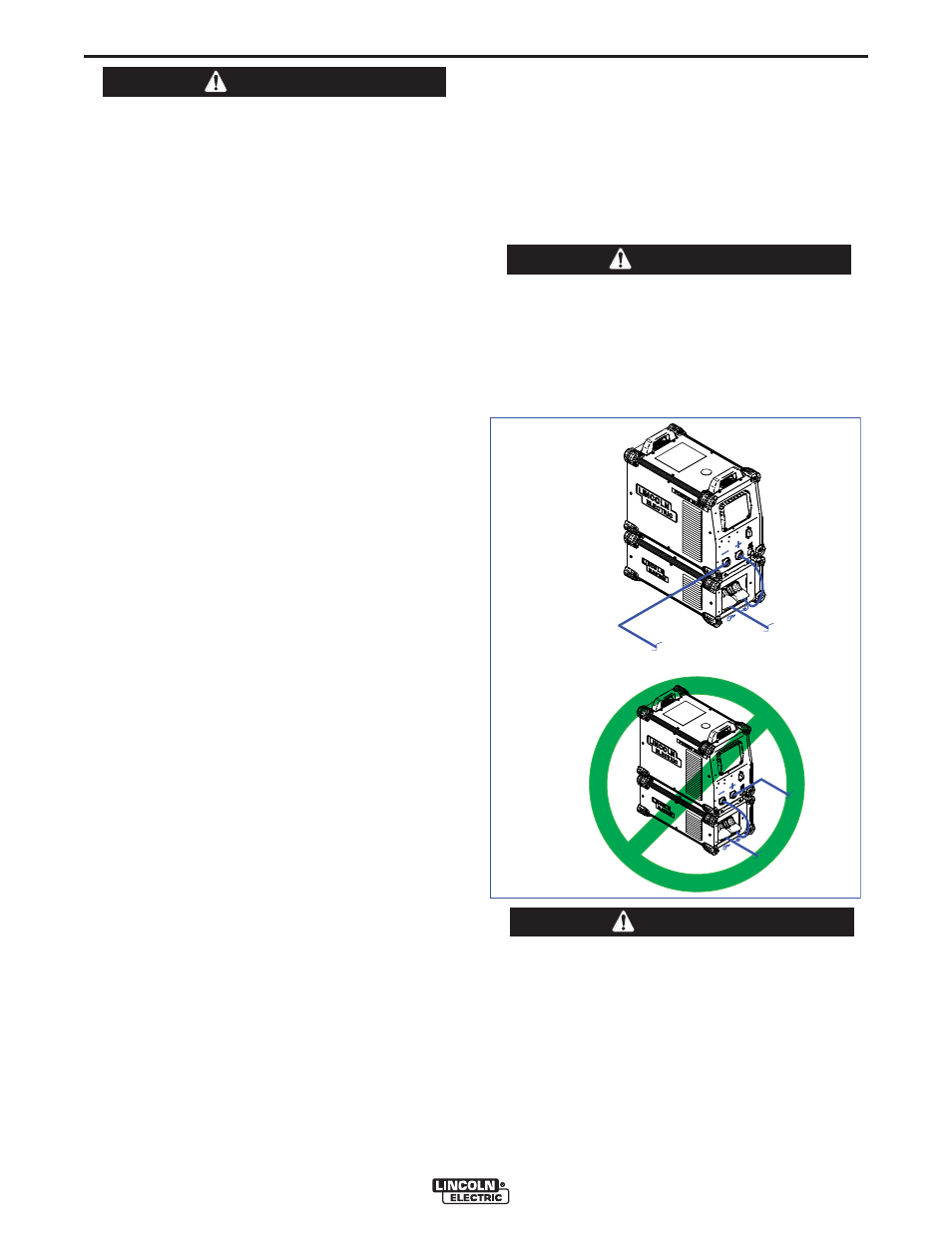
CAUTION
WARNING
TO ELECTRODE
(FEEDER)
TO WORK
NEGATIVE POLARITY
CONNECTION
(
NOT TO BE USED FOR
STT PROCESS)
TO WORK
TO ELECTRODE
(FEEDER)
FIGURE A.2