Installation, Connection diagrams, Power wave – Lincoln Electric IM10007 POWER WAVE S350 User Manual
Page 12: S350, Figure a.2 figure a.3
A-5
INSTALLATION
POWER WAVE
®
S350
A-5
CONNECTION DIAGRAMS
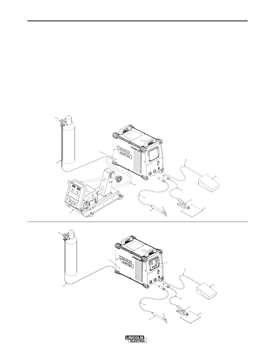
GTAW (TIG) WELDING
A user interface is required for adjusting the TIG weld-
ing settings. A Power Feed wire feeder can be used as
the user interface (Figure A.2), or a S-series user inter-
face (K2828-1) can be installed into the power source
(Figure A.3). Refer to the connection diagrams based
on the user interface that is being used. For either set-
up the K2825-1 solenoid kit is recommended for con-
trolling the gas. Alternate configurations are possible
depending on the wire feeder that is being used. Refer
to the wire feederʼs manual for alternative configura-
tions.
SMAW (STICK) WELDING
Similar to TIG welding a user interface is required for
adjusting the Stick welding settings. A Power Feed
wire feeder can be used as the user interface, or a
K2828-1 (user interface control panel) can be installed
into the power source (Figure A.4). The connection
diagram shown is based on the S-Series user inter-
face (K2828-1). In this diagram the remote control box
is optional.
GMAW (MIG) WELDING
An arclink compatible wire feeder is recommended for
Mig welding. Refer to Figure A.5 for the connection
details.
REGULATOR
FLOWMETER
FOOT AMPTROL
K87
870
WORK CLAMP
TO POSITIVE
(+) STUD
TO REMOTE CONTROL
RECEPTACLE
PF10-M
WIRE FEEDER
ARCLINK CABLE
K1543-[XX]
GAS HOSE
GAS SOLENOID KIT
TIG WITH POWER FEED USER INTERFACE
(INSIDE MACHINE)
K2825-1
TO NEGATIVE
(-) STUD
TIG TORCH
K2266-1 KIT
(INCLUDES WORK CLAMP,
ADAPTER, AND REGULATOR)
WORK PIECE
FOOT AMPTROL
K870
WORK PIECE
WORK CLAMP
TIG TORCH
K2266-1 KIT
(INCLUDES WORK CLAMP,
ADAPTER, AND REGULATOR)
TO POSITIVE
(+) STUD
TO REMOTE CONTROL
RECEPTACLE
USER INTERFACE
CONTROL PANEL
K2828-1
GAS SOLENOID KIT
TIG WITH S-SERIES USER INTERFACE
(INSIDE MACHINE)
K2825-1
TO NEGATIVE
(-) STUD
REGULATOR
FLOWMETER
GAS HOSE
FIGURE A.2
FIGURE A.3