Operation, Design features, Case front controls – Lincoln Electric IM10133 POWER WAVE R500 User Manual
Page 20
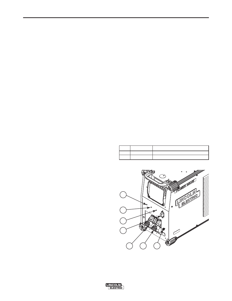
3. FEEDER STATUS LED - A two color LED that
indicates system errors. The Power Wave R500 is
equipped with two indicators. One is for the invert-
er power source, while the other indicates the sta-
tus of the feeder control system. Normal operation
is a steady green light. For more information and a
detailed listing, see the troubleshooting section of
this document or the Service Manual for this
machine. (See Troubleshooting Section for
operational functions.)
NOTE: The Power Wave R500 status light will flash
green, and sometimes red and green, for up to one
minute when the machine is first turned on. This is a
normal situation as the machine goes through a self
test at power up.
4. POWER SWITCH - Controls power to the POWER
WAVE
®
R500.
5. NEGATIVE WELD OUTPUT
6. POSITIVE WELD OUTPUT
7. VOLTAGE SENSE CONNECTOR: Allows for sep-
arate remote electrode and work sense leads.
Pin
Lead
Function
3
21
Work Voltage Sense
1
67E
Electrode Voltage Sense
B-3
OPERATION
B-3
DESIGN FEATURES
Loaded with Standard Features
• Multiple process DC output range: 5 - 550 Amps
• 200 – 600 VAC, 3 phase, 50-60Hz input power
• New and Improved Line Voltage Compensation
holds the output constant over wide input voltage
fluctuations.
• Utilizes next generation microprocessor control,
based on the ArcLink
®
platform.
• State of the art power electronics technology yields
superior welding capability.
• Electronic over current protection
• Input over voltage protection.
• F.A.N. (fan as needed). Cooling fan only runs
when needed.
• Thermostatically protected for safety and reliability.
• Ethernet connectivity.
• Panel mounted Status and Thermal LED indicators
facilitate quick and easy troubleshooting.
• Potted PC boards for enhanced ruggedness/relia-
bility.
• Enclosure reinforced with heavy duty aluminum
extrusions for mechanical toughness
• Waveform Control Technology™ for good weld
appearance and low spatter, even when welding
nickel alloys.
• Sync Tandem installed.
CASE FRONT CONTROLS
(See Figure B.1)
1. STATUS LED - (See Troubleshooting Section for
operational functions).
2. THERMAL LED - Indicates when machine has
thermal fault.
POWER WAVE
®
R500
1
4
5
7
2
3
6
FIGURE B.1