Installation, Balance check, Attention – Lincoln Electric IM10121 Mobiflex 400-MS User Manual
Page 14
A-7
INSTALLATION
MOBIFLEX 400-MS(/HE) BASE UNIT & LFA 3.1/4.1 MOBILE MANUAL/AUTOMATIC
A-7
LFA 3.1/4.1 MOBILE AUTOMATIC
The K2633-2 or K2633-4 LFA 3.1/4.1 Mobile
Automatic extraction arm contains an integrated Lamp
& Arc Sensor Kit.
Installation Steps:
See Figure A.10 for steps 1-5
1. Mount the extraction arm LFA 3.1/4.1 Mobile
Automatic (A) on the post (B) using the two bolts
M8 and two selflocking nuts M8 with washers.
2. Remove the wire bridge from the supply cable
inside the base swivel mount.
3. Connect the supply cables of the Mobiflex 400-MS(/
HE) Base Unit and the extraction arm.
4. Remove the yellow tape from both arm sections.
5. Turn the extraction arm 359° and check whether
the supply cable is long enough. If necessary, pull
the supply cable of the Mobiflex 400-MS(/HE) Base
Unit to a sufficient length.
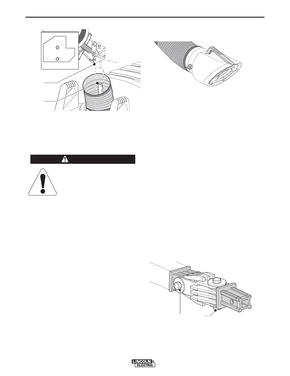
BALANCE CHECK
The extraction arms have been pre-balanced in the
factory for optimal balance and positioning. However,
they sometimes need adjustment. To check and adjust
the balance system, proceed as follows.
See Figure A.11
1. Bring the extraction hood to a horizontal position.
The hood should stay in this position.
If the extraction hood falls on its own:
(See Figure A.12)
• Cut the tie wrap of the rubber protection cover which
is applied over the hood hinge.
• Pull down the protection cover.
• Turn bolt (A) in the hood hinge clockwise to tighten
extraction hood.
• Replace the protection cover and secure it with the
spare tie wrap supplied.
If the extraction hood does not stay to a horizon-
tal position (left/right):
(See Figure A.12)
• Cut the tie wrap of the rubber protection cover which
is applied over the hood hinge.
• Pull down the protection cover.
• Turn bolt (B) in the hood hinge clockwise to tighten
horizontal movement.
• Replace the protection cover and secure it with the
spare tie wrap supplied.
FIGURE A.10
B
A
Do not remove the yellow tape
attaching both arm sections.
------------------------------------------------------------------------
ATTENTION
FIGURE A.11
FIGURE A.12
A
B