Operation, Wire drive configuration, Warning – Lincoln Electric IM10096 POWER MIG 256 User Manual
Page 18
B-6
B-6
OPERATION
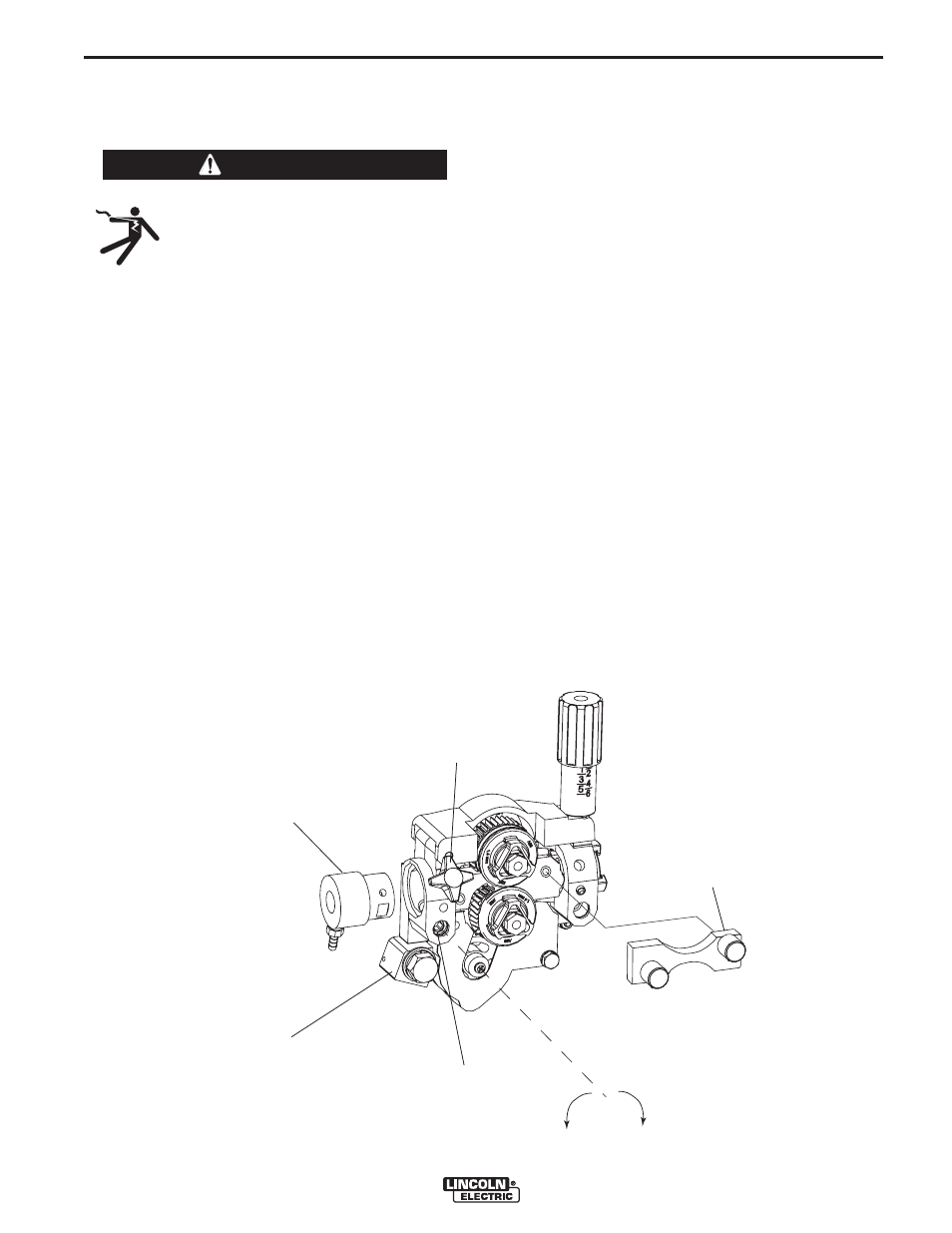
GUN RECEIVER BUSHING
LOOSEN
TIGHTEN
THUMB SCREW
OUTER WIRE GUIDE
SOCKET HEAD
CAP SCREW
CONNECTOR BLOCK
WIRE DRIVE CONFIGURATION
(See Figure B.5)
Changing the Gun Receiver Bushing
ELECTRIC SHOCK can kill.
• Turn the input power OFF at the weld-
ing power source before installation
or changing drive rolls and/or guides.
• Do not touch electrically live parts.
• When inching with the gun trigger, electrode and
drive mechanism are "hot" to work and ground
and could remain energized several seconds
after the gun trigger is released.
• Only qualified personnel should perform mainte-
nance work.
------------------------------------------------------------------------
Tools required:
• 1/4" hex key wrench.
Note: Some gun bushings do not require the use of
the thumb screw.
1. Turn power off at the welding power source.
2. Remove the welding wire from the wire drive.
3. Remove the thumb screw from the wire drive.
4. Remove the welding gun from the wire drive.
Figure B.5
POWER MIG
®
256
5. Loosen the socket head cap screw that holds the
connector bar against the gun bushing.
Important: Do not attempt to completely
remove the socket head cap screw.
6. Remove the outer wire guide, and push the gun
bushing out of the wire drive. Because of the pre-
cision fit, light tapping may be required to remove
the gun bushing.
7. Disconnect the shielding gas hose from the gun
bushing, if required.
8. Connect the shielding gas hose to the new gun
bushing, if required.
9. Rotate the gun bushing until the thumb screw hole
aligns with the thumb screw hole in the feed plate.
Slide the gun receiver bushing into the wire drive
and verify the thumb screw holes are aligned.
10. Tighten the socket head cap screw.
11. Insert the welding gun into the gun bushing and
tighten the thumb screw.
WARNING