2 serial device connection, Figure 3-10: lan connection – IEI Integration AFL-056A-LX v2.10 User Manual
Page 48
AFOLUX LX Panel PC
Page 35
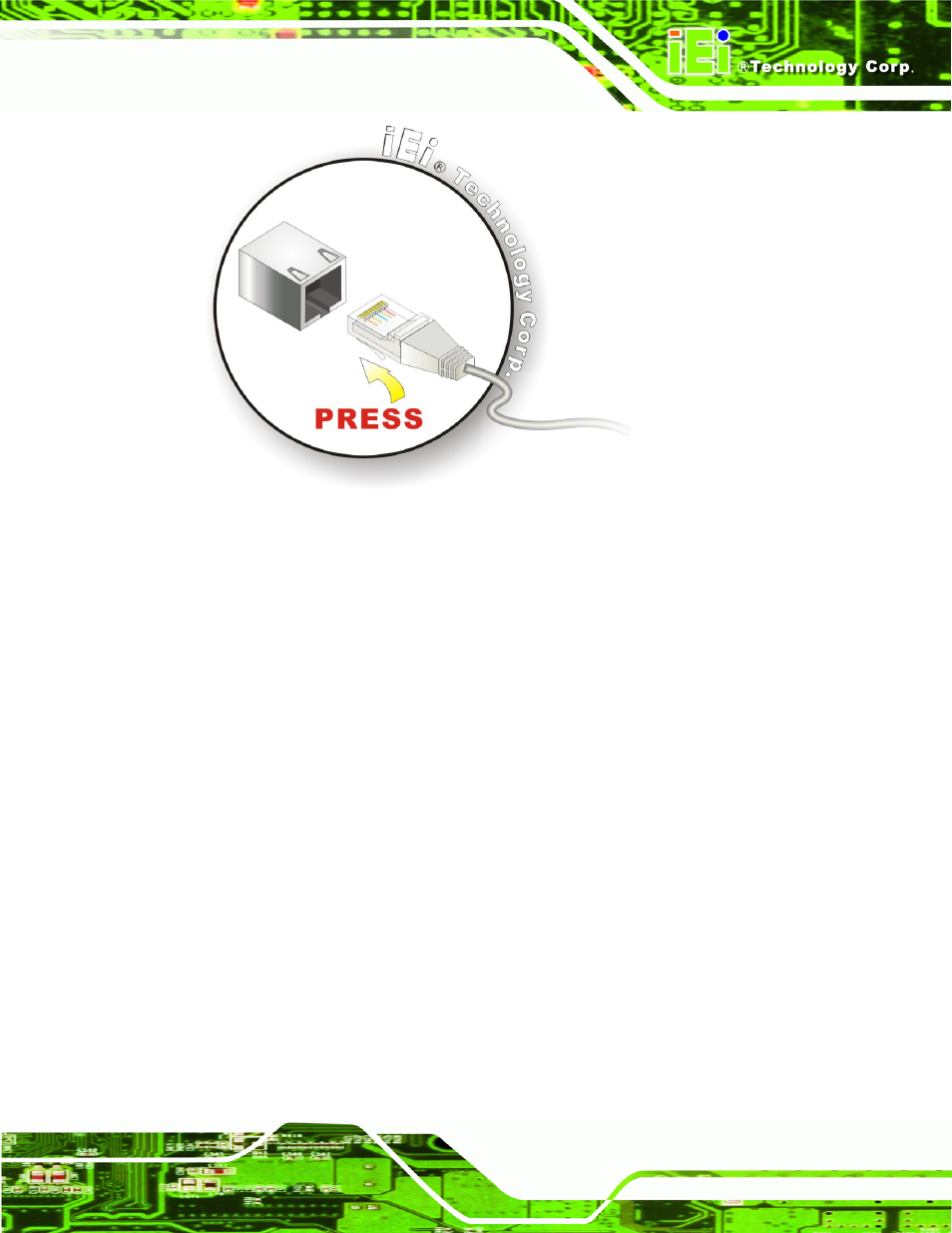
Figure 3-10: LAN Connection
Step 3:
Insert the LAN cable RJ-45 connector.
Once aligned, gently insert the LAN
cable RJ-45 connector into the onboard RJ-45 connector.
Step 0:
3.8.2 Serial Device Connection
The AFOLUX LX has two serial device connectors on the bottom panel. The two serial
device slots (RJ-45) connect to a cable with a standard DB-9 connector at the other end
(cables included). Follow the steps below to connect a serial device to the AFOLUX LX
panel PC.
Step 1:
Locate the RJ-45 connector
. The location of the RJ-45 serial port connector is
shown in Chapter 2. The RJ-45 connectors for the serial ports can be identified
easily as the RJ-45 for the network has two LEDs on the port, while the
connectors for the serial cables don’t.
Step 2:
Insert the RJ-45 to DB-9 cable.
Step 3:
Insert the serial connector
.
Insert the DB-9 connector of a serial device into
the DB-9 connector on the cable. See Figure 3-11.