7 rs-422/485 serial port connector, Figure 3-14: rs-232 serial port pinout location, Table 3-5: rs-232 serial port pinouts – IEI Integration TANK-101B-D525_N455 v1.02 User Manual
Page 37: See table 3-5 and figure 3-14
TANK-101B/BW Embedded System
Page 26
Pin Description
Pin Description
3 TX
8 CTS
4 DTR
9 RI
5 GND
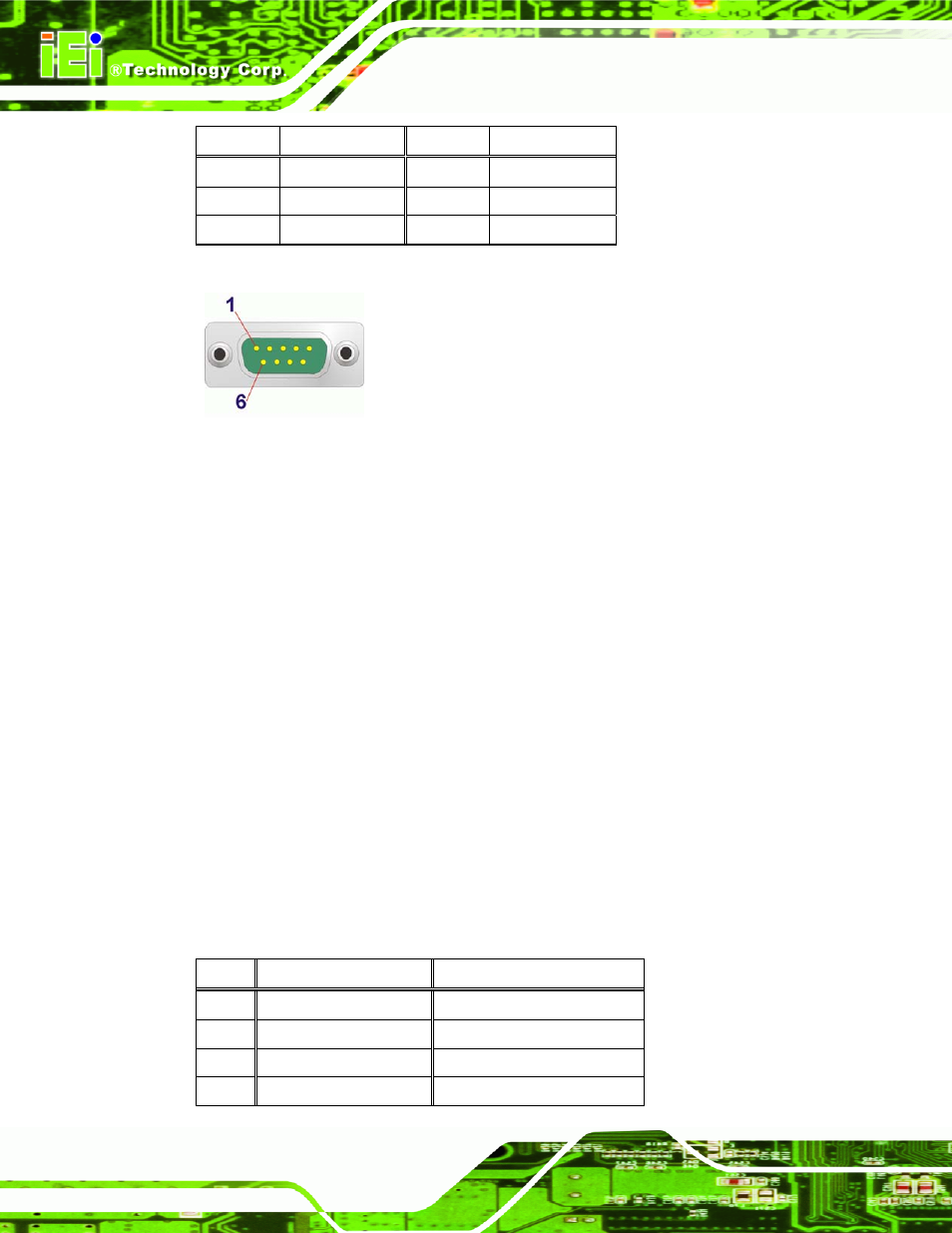
Table 3-5: RS-232 Serial Port Pinouts
Figure 3-14: RS-232 Serial Port Pinout Location
3.7.7 RS-422/485 Serial Port Connector
CN Label:
COM3
CN Type:
DB-9 connector
CN Location:
CN Pinouts:
See Error! Reference source not found. and Figure 3-15
The RS-422/485 serial port device can be attached to the DB-9 port on the rear panel.
Step 1:
Locate the DB-9 connector
. The location of the DB-9 connector is shown in
.
Step 2:
Insert the serial connector
.
Insert the DB-9 connector of a serial device into
the DB-9 connector on the external peripheral interface. See Figure 3-13.
Step 3:
Secure the connector
. Secure the serial device connector to the external
interface by tightening the two retention screws on either side of the connector.
Pin Description
(RS-422)
Description (RS-485)
1 RXD422
#
N/A
2 RXD422
+
N/A
3
TXD422 +
TXD485 +
4
TXD422 #
TXD485 #