5 internal peripheral device connections, 1 sata drive connection, Nternal – IEI Integration IMBA-G410 v1.01 User Manual
Page 68: Eripheral, Evice, Onnections, Figure 4-13: usb power select jumper location, Table 4-7: usb power select jumper settings, Figure 4-3, Figure 4-3: cpu socket load plate
548/17/2011158
Page 54
IMBA-G410 ATX Motherboard
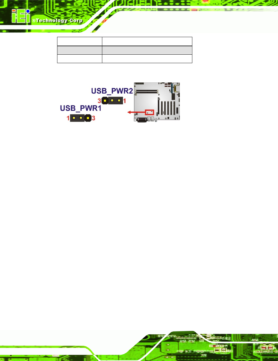
Setting Description
Short 1-2
+5 V (Default)
Short 2-3
+5VSB
Table 4-7: USB Power Select Jumper Settings
Figure 4-13: USB Power Select Jumper Location
4.5 Internal Peripheral Device Connections
This section outlines the installation of peripheral devices to the onboard connectors.
4.5.1 SATA Drive Connection
The IMBA-G410 is shipped with two SATA drive cables and one SATA drive power cable.
To connect the SATA drives to the connectors, please follow the steps below.
Step 1:
Locate the connectors. The locations of the SATA drive connectors are shown
in Chapter 3.
Step 2:
Insert the cable connector. Press the clip on the connector at the end of the
SATA cable and insert the cable connector into the on-board SATA drive
connector. See
66
Figure 4-14.