Before you begin, Installation instruction – WARN ZEON CONTROL PACK RELOCATION KIT 78 User Manual
Page 5
WARN INDUSTRIES
5 89959A0
BEFORE YOU BEGIN
Tools Required
•
Torx Driver Set
• Ratchet/Wrench
Set
(Standard/Metric)
•
Drill and Drill Bit Set
• Wire
Cutters
•
Wire Strippers/Wire Crimps
•
Torque Wrench (30 lb. ft. capacity)
• Zip
Ties
•
Cable Protection (i.e., flexible electrical conduit or electrical tape)
Torque Specifi cations
Please use the recommended torque specifi cations when assembling this product unless otherwise
specifi ed in the instructions.
Inspect all nuts and bolts on all related hardware periodically. Tighten all nuts that appear to be loose. Stripped, fractured, or bent bolts
or nuts need to be replaced.
FASTENER SIZE
(Grade 5)
FASTENER TORQUE
FASTENER SIZE
(Class 8.8)
FASTENER TORQUE
lb-ft (N.m)
lb-ft
(N.m)
1/4" 8
(11)
M4
(2)
3
5/16" 17
(23)
M5
(4.5)
6
3/8" 30
(40)
M6
(7.5)
10
7/16”
48
(66)
M8
(18)
25
1/2" 74
(100)
M10
(37)
50
9/16”
106
(144)
5/8" 148
(200)
3/4”
269
(364)
WARN INDUSTRIES
6
89959A0
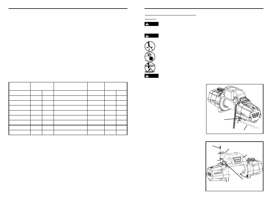
INSTALLATION INSTRUCTION
REMOVE CONTROL PACK FROM
WINCH
WARNING
To prevent serious injury or death. Always
place the supplied terminal boots on wires and terminals as
directed by the installation instructions.
WARNING
To prevent serious injury or death from
electrical fi re:
Never route electrical cables across sharp edges.
Never route electrical cables near parts that get
hot.
Never route electrical cables through or near
moving parts.
Avoid pinch and wear/abrasion points when
installing all electrical cables.
WARNING
Always insulate and protect all exposed wiring
and electrical terminals.
1.
Disconnect the vehicle battery cables,
negative terminal first. All work with electrical
wires and cables must be completed with the
battery completely disconnected from the
vehicle wiring.
2.
Disconnect the ground cable on the under
side of the winch (see figure 1). Make sure the
small black wire that connects to the control
pack is disconnected and hanging freely.
3.
Remove the top buss bar cover by unscrewing
the fastener holding it in place. Retain
fastener for later use.
4.
Remove the three motor terminal nuts and
lock washers that secure the buss bars to
the motor. Retain the terminal nuts and lock
washers for future step.
Figure 1
Figure 2
Buss Bar Cover
Control Pack
Remove
Terminal
Nuts
Small Black
Wire
Buss Bars
Disconnect Ground Wire