Vanguard WRM-10 User Manual
Page 13
REV 2 WRM-10 USER’S MANUAL
10
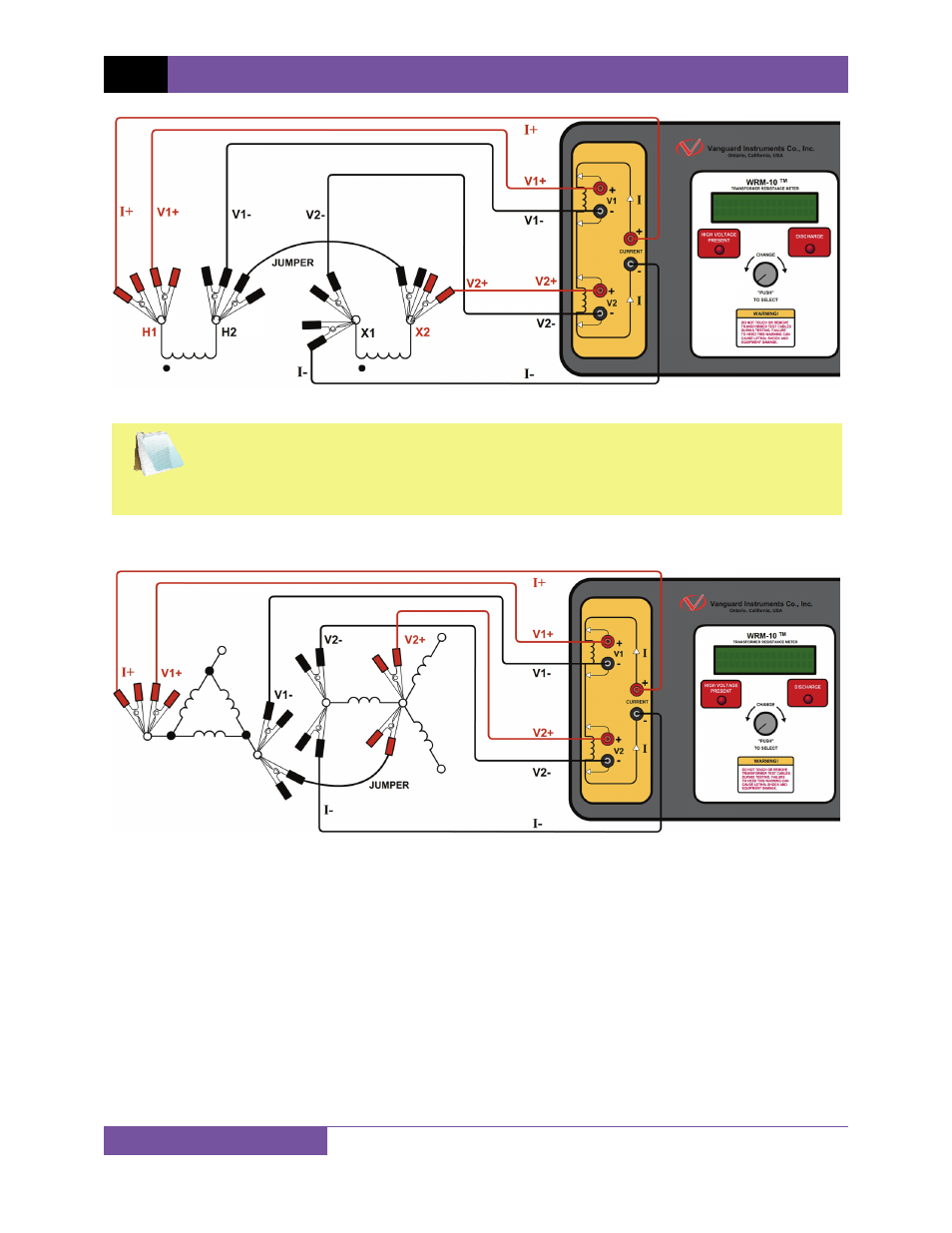
Figure 6. Typical WRM-10 Connections Diagram #2
NOTE
The above figure illustrates the simultaneous testing of both the high and low
windings on a single-phase transformer. When measuring two channels, the above
cable connection is recommended since it will speed up the testing process.
Figure 7. Typical Dual Winding Connections Diagram
See also other documents in the category Vanguard Accessories for electrical:
- Resistor Transducer Adapter 9095-UC (7 pages)
- Accu-Ohm 200 S2 (4 pages)
- Accu-Trans (28 pages)
- ATO-400 (43 pages)
- ATO-400P (44 pages)
- Auto-Ohm (22 pages)
- Auto-Ohm 100_200 s2 (31 pages)
- Auto‐Ohm 200 S3 (66 pages)
- DMOM-100 (35 pages)
- DMOM-100_200 s2 (42 pages)
- DMOM-200 (33 pages)
- Herculito (17 pages)
- ATRT-01 S2 (59 pages)
- ATRT-01_01B S3 (88 pages)
- ATRT-01_01B_01D (31 pages)
- ATRT-03_03A (114 pages)
- ATRT-03_03A S2 (147 pages)
- CVT-765 (46 pages)
- Tri-Phase (155 pages)
- CBCT (14 pages)
- CBPS-300 (16 pages)
- CT-3500 (24 pages)
- CT-3500 S2 (53 pages)
- CT-6500 (69 pages)
- CT-6500 S2 (82 pages)
- CT-7000 (83 pages)
- CT-7000 S2 (108 pages)
- CT-7000 S3 (137 pages)
- CT-7500 (76 pages)
- CT-7500 S2 (110 pages)
- CT-8000 (120 pages)
- CT-8000 S3 (145 pages)
- DigiTMR (86 pages)
- DigiTMR S2 (123 pages)
- DigiTMR S2 PC (31 pages)
- MCCB-250 (17 pages)
- UPS S2 (13 pages)
- EZCT-2000 (68 pages)
- EZCT-2000 (45 pages)
- EZCT-2000A (103 pages)
- EZCT-2000B (118 pages)
- EZCT-2000C Plus (119 pages)
- EZCT-S2 (66 pages)
- EZCT-S2A (98 pages)
- IRM-5000P (58 pages)